
Optical reading method

An optical reading and semiconductor technology, applied in the field of optical reading, can solve the problems of deviation of wavelength region, inability to obtain strong light emission, etc.

Inactive Publication Date: 2011-11-23
METRO ELECTRONICS
View PDF5 Cites 1 Cited by
  • Summary
  • Abstract
  • Description
  • Claims
  • Application Information

AI Technical Summary

Problems solved by technology

[0016] However, the inventors of the present invention optically read and tested the information of the printed layer (information pattern) using the phosphor invisible ink of Patent Document 1, and the information cannot be read in many cases.
The reason for this is considered to be that, in the technique of Patent Document 1, when information using invisible ink is read, the wavelength range of light emitted by the excitation light deviates and strong light emission cannot be obtained.

Method used


Image

  • Optical reading method
  • Optical reading method
  • Optical reading method

Examples


no. 1 Embodiment approach

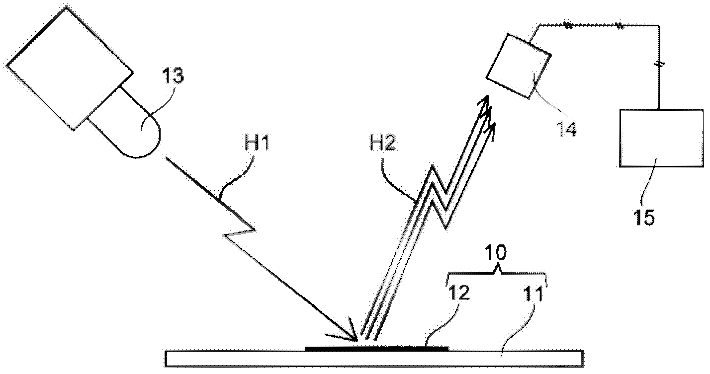
[0040] First, the configuration for implementing the optical reading method will be described. figure 1 It is a conceptual diagram for explaining the optical reading method of this embodiment. exist figure 1 Among them, the information recording card 10 is composed of an information recording medium (or may be a managed object) 11 and an information pattern 12 printed on the information recording medium 11 such as an invisible barcode or a QR code.

[0041] The information recording medium 11 is, for example, a card body made of a vinyl chloride-based thin plate in which a white pigment such as titanium oxide is dispersed and held, and has a property of reflecting infrared rays, visible rays, and ultraviolet rays. As the information recording medium 11, for example, cash cards, various prepaid cards, telephone cards, pass cards, health insurance cards, etc. are applied.

[0042] In the information pattern 12, an invisible information pattern is printed on an information reco...

no. 2 Embodiment approach

[0059] This embodiment has a configuration in which semiconductor quantum dots are thermally shrunk, light emission having a wavelength shifted to the short wavelength side is performed from the heat-shrunk semiconductor quantum dots, and the shorter wavelength among the shifted wavelengths is utilized. The photosensor having sensitivity on the wavelength side part receives the above-mentioned light emission, and reads the above-mentioned information pattern. In addition, the same code|symbol is attached|subjected to the part which overlaps with 1st Embodiment, and description is abbreviate|omitted.

[0060] In this embodiment, a cooling mechanism (not shown) for thermally shrinking the semiconductor quantum dots is provided by cooling the semiconductor quantum dots. Here, the cooling mechanism refers to a mechanism for blowing air at 0° C. to 10° C. to the information pattern 12 to cool the information pattern 12 to around 0° C. to thermally shrink the semiconductor quantum d...


PUM


Abstract

Disclosed is an optical reading method with which can be realized a system that compensates for handling of an information pattern not recognizable to the naked eye, wherein a nonvisible information pattern such as a bar code or a QR code is printed on an information recording medium or an object to be managed, and that provides high security or guaranteed product quality. When an information recording medium (11) having an information pattern (12) is placed in or transported to a prescribed position, the information pattern (12) is irradiated with excitation light (H1), which is emitted from a light-emitting diode (13) and has higher energy than the band gap of a semiconductor quantum dot, and the semiconductor quantum dot is thermally expanded. Then, light is emitted from the thermally-expanded quantum dot with a wavelength which transitions to the long-wavelength side compared to the wavelength emitted from the quantum dot prior to thermal expansion, this light beam is received by an optical sensor (14), which has a sensitivity to the longer wavelength portion of light which is emitted and transitions to the long-wavelength side, and the information pattern (12) is read by an information judgment unit (15).

Description

technical field [0001] The present invention relates to an optical reading method for reading information patterns such as barcodes and QR codes printed on information recording media or managed objects. Background technique [0002] In recent years, in the management of various articles, various prepaid cards, access cards, etc., information patterns such as barcodes and QR codes are printed and read by optical reading devices to perform management and authentication checks. A variety of security systems have been proposed that provide anti-counterfeit measures to these information patterns and read them with an optical reading system to determine whether or not the information patterns are counterfeit. [0003] For example, a security system has been implemented in which an invisible information pattern such as a barcode is printed with an invisible ink (ink) containing a fluorescent substance, and a semiconductor laser is irradiated to the information pattern to excite th...

Claims


Application Information

Patent Timeline
Patent Type & Authority Applications(China)
IPC IPC(8): G06K7/10C09K11/08C09K11/56C09K11/59C09K11/62C09K11/88G06K7/12G06K17/00
CPCC09K11/883C09K11/565G06K7/12
Inventor 中西干育
Owner METRO ELECTRONICS
Learn More