Vertical Mill Sealed Feeder

A technology of feeder and vertical mill, applied in the direction of conveyor objects, containers, packaging, etc., can solve the problems of increased power consumption, time-consuming and labor-intensive, hidden safety hazards, etc., to improve production efficiency, reduce production costs, and power consumption saving effect

Active Publication Date: 2011-11-30
SICHUAN ESHENG CEMENT GROUP
View PDF3 Cites 9 Cited by
  • Summary
  • Abstract
  • Description
  • Claims
  • Application Information

AI Technical Summary

Problems solved by technology

[0004] In the existing vertical mill system, after one year of operation of the air-locking feeder, the wear of the blades will be very serious, reaching about 20mm, and the air-locking effect will be reduced by about 80%, thus losing the air-locking effect, and the raw material will The output will drop by 10 to 20 tons when the mill is installed, and the power consumption per ton of the raw material vertical mill system will increase by about 1.5 degrees. In addition to the increase in the air volume of the exhaust fan at the kiln tail, the comprehensive power consumption per ton of clinker will increase by about 3 degrees. The air lock feeder transports large granular materials, so the phenomenon of material jams often occurs during operation, and the vibration is very large during operation. The support rod of the reducer base is often broken, and the reducer and the motor are overturned under the action of force. , there is a large safety hazard; when the particle size of the limestone is large, it is prone to jamming, and the annual average number of jamming is about 20 times. Therefore, frequent maintenance and overall replacement of the lock air feeder are required, which is time-consuming and laborious.

Method used


Image

  • Vertical Mill Sealed Feeder
  • Vertical Mill Sealed Feeder

Examples


Embodiment Construction

[0014] Below in conjunction with accompanying drawing, the present invention is described in detail.

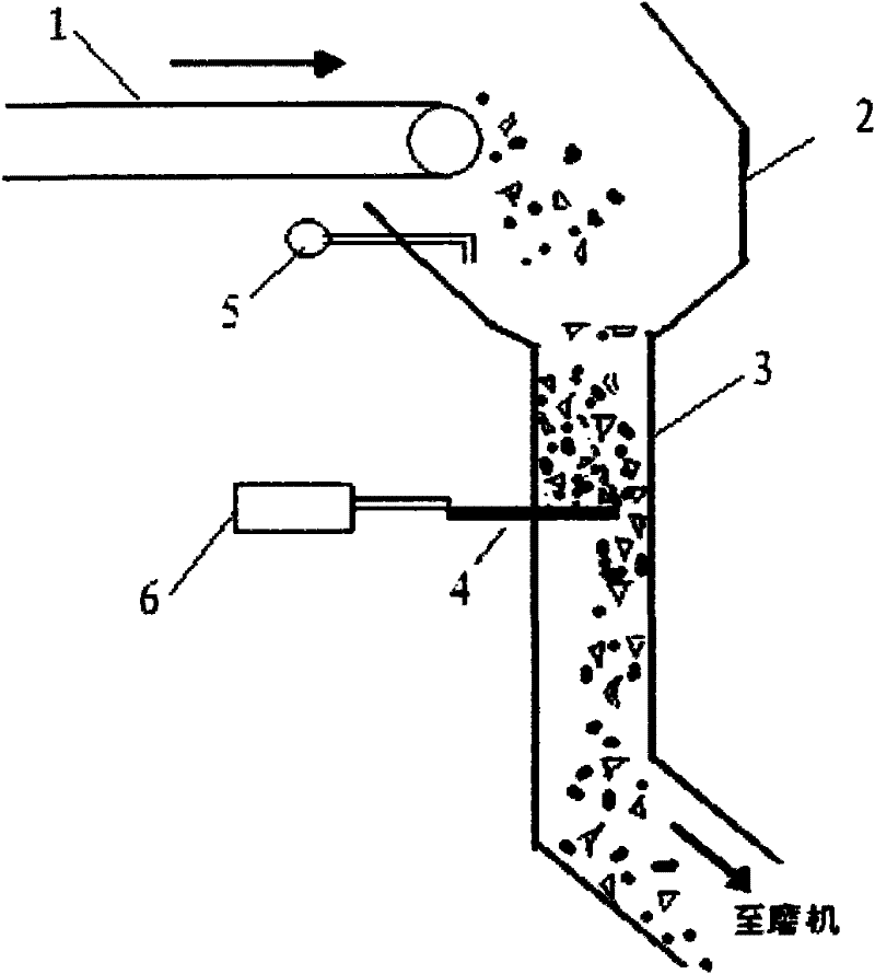
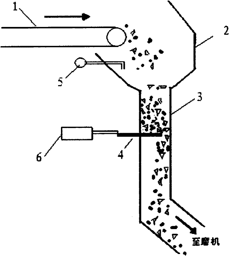
[0015] Such as figure 1 As shown, according to a preferred embodiment of the present invention, a vertical mill sealed feeder includes: a grinding belt 1; a feeding pipe 2, which is arranged below the grinding belt 1; a straight feeding pipe 3, which is connected below the feeding pipe 2; the horizontal inserting plate 4, which is arranged in the middle section of the feeding straight pipe 3, and the horizontal inserting plate 4 extends into the length of the feeding straight pipe 3 It can be adjusted by the cylinder 6, so that the gap between the horizontal plate 4 and the straight feeding pipe 3 forms a feeding space for materials to pass through; the negative pressure gauge 5 is installed above the feeding pipe 2, so that The negative pressure gauge 5 is connected with the PLC and the central control, and the negative pressure gauge is provided with an upper limit value o...


PUM


Abstract

The invention provides a hermetic feeder for a vertical mill. The feeder comprises a mill feed belt, a blanking pipe, a blanking straight pipe, a horizontal insertion plate and a negative pressure meter, wherein the blanking pipe is arranged below the mill feed belt; the blanking straight pipe is connected below the blanking pipe; the horizontal insertion plate is arranged in the middle section of the blanking straight pipe; the length of the horizontal insertion plate stretching into the blanking straight pipe can be adjusted by an actuating mechanism, so that a blanking space is formed by agap between the horizontal insertion plate and the blanking straight pipe and is used for materials to pass through; and the negative pressure meter is arranged above the blanking pipe, is connected with an automatic control system and a central controller, and is provided with an upper limit value and a lower limit value, so that negative pressure starts dropping from a normal value when the blanking straight pipe is blocked, the automatic control system makes the actuating mechanism start acting to open the horizontal insertion plate when the negative pressure reaches the lower limit value,the negative pressure rises due to automatic dredging of material scouring, the automatic control system makes the actuating mechanism close the horizontal insertion plate when the negative pressure reaches the upper limit value, and the negative pressure is restored to the normal value.

Description

technical field [0001] The invention relates to a vertical mill sealed feeder. Background technique [0002] Each raw material vertical mill for cement production is generally equipped with an air lock feeder. In all series of air lock feeder systems, air lock and feeding are both an important point and a difficult point; No effective air lock equipment has been designed by the Type Mill Research Institute. [0003] If the internal blades of the airlock feeder are worn out, the airlock effect will be greatly reduced, and a large amount of cold air will enter the vertical mill, which not only reduces the heat required for the raw material grinding of the vertical mill, but also increases the raw meal circulation fan. And the kiln exhaust fan handles the air volume, in other words, it not only reduces the output of the raw meal vertical mill, but also increases the power consumption. Therefore, the air lock requirements of the feed inlet of the raw meal vertical mill are rel...

Claims


Application Information

Patent Timeline
Patent Type & Authority Applications(China)
IPC IPC(8): B65G47/18B65D88/64
Inventor 骆玉刚童敬平周永洪
Owner SICHUAN ESHENG CEMENT GROUP
Why Eureka
Try Eureka