
Aerobic membrane bioreactor and process

A membrane bioreactor and process technology, applied in chemical instruments and methods, water/sewage multi-stage treatment, water/sludge/sewage treatment, etc. It can solve the problems of large quantity and other problems, so as to achieve the effect of remarkable and efficient operation effect, small equipment footprint and simple process design.

Inactive Publication Date: 2011-11-30
上海膜达克环保工程有限公司
View PDF3 Cites 8 Cited by
  • Summary
  • Abstract
  • Description
  • Claims
  • Application Information

AI Technical Summary

Problems solved by technology

[0003] The MBR system and its process have many advantages, but there are the following disadvantages: 1) the system has a large oxygen demand and high energy consumption; 2) the membrane surface is easy to clog; 3) the membrane module is expensive
However, in practical engineering applications, hollow fiber membranes have several obvious technical defects: 1) the fiber filaments are easily broken during the vigorous stirring process; Density, so that the fiber filaments are easily blocked by the sludge in the reaction tank, and the blockage of the junction between the membrane filaments and the sealant at both ends of the membrane module is the most common sludge blockage
After clogging, the flux of the membrane drops sharply, and the water outlet is unstable, which may easily cause fiber breakage and increase the difficulty of cleaning

Method used


Image

  • Aerobic membrane bioreactor and process
  • Aerobic membrane bioreactor and process

Examples


Embodiment Construction

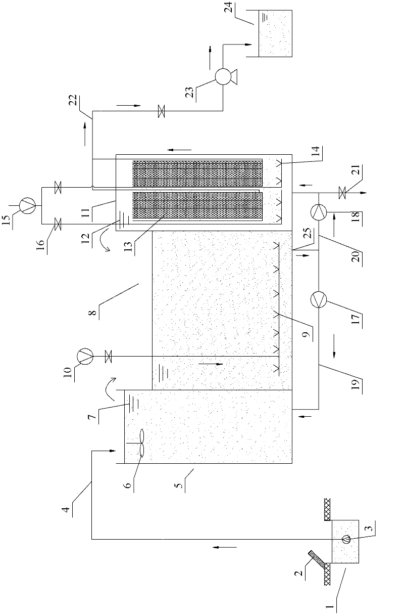
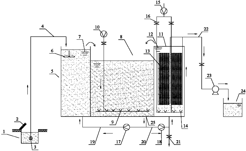
[0029] see figure 1 , is the aerobic membrane bioreactor involved in the present invention. It includes water collecting well 1, anoxic pool 5, aerobic pool 8, membrane pool 11 and clear water pool 24 which are set separately. The water collection well 1 is arranged under the ground surface, and a fine grid 2 is arranged on the ground surface, and the size of the grid 2 is not more than 1mm. A lift pump 3 is arranged in the water collection well 1, and the sewage can be extracted and transported through the water inlet pipe 4, and the water inlet pipe 4 above the upper opening of the anoxic pool 5. An agitator 6 is set in the anoxic pool 5 . The aerobic pool 8 is located between the anoxic pool 5 and the membrane pool 11 . The liquid levels of the anoxic pool 5 and the membrane pool 11 are all higher than the liquid level of the aerobic pool 8, and the side of the anoxic pool 5 near the aerobic pool 8 is provided with a first upper overflow port 7, and the membrane pool 11 ...


PUM

PropertyMeasurementUnit
sizeaaaaaaaaaa

Abstract

The invention discloses an aerobic membrane bioreactor and a technology thereof. The aerobic membrane bioreactor comprises an anoxic tank, an aerobic tank and a membrane tank. The anoxic tank is provided with an upper opening and a first upper overflow port. Liquid level of the anoxic tank is higher than that of the aerobic tank. An outlet is arranged on the bottom of the aerobic tank. The outletis respectively connected to the bottom of the anoxic tank and the bottom of the membrane tank. The membrane tank is provided with a second upper overflow port. Liquid level of the membrane tank is higher than that of the aerobic tank. A membrane component is arranged in the membrane tank. The membrane tank is connected to a clean water tank. According to the invention, the membrane tank is separated from the aerobic reaction tank. The aerobic membrane bioreactor is suitable for large-batch sewage processing, and is convenient to maintain. Liquid levels of the anoxic tank and the membrane tank are higher than that of the aerobic tank, and communications between the tanks are realized through overflowing. Sludge concentration in the membrane tank can be controlled effectively. According tothe invention, high accumulating density of the components can be maintained, quality of produced water is good, area occupied by the equipment is small, amount of discharged sludge is small, nitration capacity of the bioreactor is good, and the structure of the bioreactor is simple.

Description

technical field [0001] The invention belongs to the technical field of sewage treatment, and in particular relates to an aerobic membrane bioreactor and a process for the membrane bioreactor. Background technique [0002] Membrane technology, as one of the most promising high-tech technologies in the 21st century, is called "the third industrial revolution" by environmental industry experts at home and abroad. Membrane bioreactor (MBR) technology has been developed in the past 20 years and is widely used in wastewater treatment as an engineering technology. MBR has obvious technical advantages in the future activated sludge improvement process and can be used for municipal wastewater, domestic wastewater, various The advanced treatment of a variety of industrial wastewater and slightly polluted raw water, as well as the field of sewage reuse, has a huge market capacity. [0003] The MBR system and its process have many advantages, but there are the following disadvantages: ...

Claims


Application Information

Patent Timeline
Patent Type & Authority Applications(China)
IPC IPC(8): C02F9/14
Inventor 向阳罗春译
Owner 上海膜达克环保工程有限公司
Learn More