Multi-stage heat recovery compound dehumidification fresh air air handler

A heat recovery and processor technology, applied in the direction of shielding with air flow, space heating and ventilation, space heating and ventilation details, etc., can solve the problems of increasing regeneration energy consumption, high regeneration temperature, and increased energy consumption, etc. Achieve the effect of reducing cooling energy consumption, reducing regeneration temperature, and reducing heating energy consumption

Inactive Publication Date: 2011-11-30
HUNAN UNIV OF SCI & TECH
View PDF9 Cites 30 Cited by
  • Summary
  • Abstract
  • Description
  • Claims
  • Application Information

AI Technical Summary

Problems solved by technology

For hot and humid areas, fresh air requires a large amount of dehumidification. Although traditional condensation dehumidification can guarantee the required amount of dehumidification, the required refrigerant temperature is low, which will lead to increased energy consumption of the refrigeration system due to performance degradation, and will inevitably lead to excessive fresh air. It is cold and needs to be reheated, which further increases the energy consumption of the fresh air treatment of the air conditioner
However, the use of single-stage rotor drying and dehumidification will not cause the fresh air to be overcooled, but it is usually difficult to achieve the required dehumidification capacity, or the required regeneration temperature is very high, which greatly increases the energy consumptio

Method used


Image

  • Multi-stage heat recovery compound dehumidification fresh air air handler
  • Multi-stage heat recovery compound dehumidification fresh air air handler
  • Multi-stage heat recovery compound dehumidification fresh air air handler

Examples


Embodiment approach

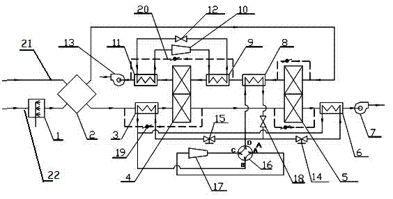
[0033] Such as Figure 5 As shown in the winter operation mode, the evaporative cooler 1, the pre-cooling dehumidifier 3, the drying runner 4, the sensible heat recovery runner 5, and the high-temperature heat pump heat recovery system will all stop running.

[0034] The air treatment process is as follows: outdoor fresh cold air enters the plate heat exchanger 2 to exchange heat with the indoor exhaust air with a higher temperature from the building, and the temperature rises. The preheated fresh air enters the air supply temperature regulator 6 through the bypass pipe, is heated to the air supply temperature by the high-temperature refrigerant vapor from the low-temperature heat pump, and then is sent into the room through the air supply fan 7.

[0035] The building exhaust air treatment process is: the building exhaust air passes through the plate heat exchanger 2, transfers energy to the fresh air, lowers the temperature, and then enters the low-temperature heat pump heat ...


PUM


Abstract

The invention discloses a multilevel heat recovery composite dehumidifying fresh air treatment machine, which comprises an air treatment path consisting of a plate heat exchanger, a precooling dehumidifier, a drying rotary wheel, a moisture heat recovery rotary wheel, an air feed temperature regulator and an air feed fan which are connected in series in turn through an air pipe, and an air regeneration path consisting of an evaporative cooler, a plate heat exchanger, a moisture heat recovery rotary wheel, a low-temperature heat pump heat recovery device, a high-temperature heat pump condenser, a drying rotary wheel, a high-temperature heat pump evaporator and a regenerating fan which are connected in series in turn. Due to multilevel heat recovery, heating energy consumption of regenerating air and cooling energy consumption of treating air are reduced, and the aim of saving energy is fulfilled. Meanwhile, due to two-stage combined dehumidification, the dehumidifying capacity of the set can be effectively improved, and the air treatment machine is applicable to air conditioning in summer and heating in winter for various public buildings, commercial buildings and industrial buildings, and is suitable for fresh air treatment for a large central air-conditioning system and particularly suitable for fresh air treatment for an independent temperature and humidity control air-conditioning system in a warm and humid area.

Description

technical field [0001] The invention relates to an air treatment device, in particular to a multi-stage heat recovery compound dehumidification fresh air air treatment machine. Background technique [0002] Saving energy consumption, reducing the discharge of environmental pollutants, and realizing sustainable development of energy are topics of common concern in the world today. Building energy consumption occupies a considerable proportion in the total energy consumption of the society. In our country, this proportion is close to 30%. Therefore, reducing building energy consumption has become one of the important tasks of energy conservation and emission reduction in our country. Air-conditioning energy consumption is the main body of building energy consumption. Saving air-conditioning energy consumption, especially air-conditioning fresh air treatment energy consumption, is an effective way to achieve building energy conservation. [0003] Independent control of tempera...

Claims


Application Information

Patent Timeline
IPC IPC(8): F24F3/00F24F3/14F24F12/00
Inventor 郝小礼黎娇冯禹王海桥刘何清朱昌宙
Owner HUNAN UNIV OF SCI & TECH
Why Eureka
Try Eureka