Inductively coupled plasma ion source gas protection device

A gas protection device, plasma technology, applied in the direction of ion source/gun, electrical components, circuits, etc., can solve the problems of poor background signal precision, insufficient heat dissipation, ICP torch extinguishing, etc., to improve the linear correlation coefficient and The effect of detection limit, reduction of background equivalent concentration, and low operating cost

Inactive Publication Date: 2014-01-01
NINGBO ACAD OF SCI & TECH FOR INSPECTION & QUARANTINE
View PDF3 Cites 3 Cited by
  • Summary
  • Abstract
  • Description
  • Claims
  • Application Information

AI Technical Summary

Problems solved by technology

[0004] In ICP-MS analysis, the problem of low-mass mass spectral interference has been a major constraint, resulting in poor detection limits for many elements and poor precision due to background signal fluctuations
But this kind of protective device for plasma torch with plasma arc and powder particle flow is not suitable for use in inductively coupled plasma mass spectrometry. On the one hand, it cannot completely isolate the plasma from the outside world. The inert gas can also easily cause the inductively coupled plasma to be unable to maintain, causing the ICP torch to go out, and due to the extremely high temperature of the ICP torch, the structure and gas filling angle of the protection device for the plasma arc and powder particle flow used in this plasma spray gun lead to insufficient heat dissipation Well, it is easy to cause damage to the instrument

Method used


Image

  • Inductively coupled plasma ion source gas protection device
  • Inductively coupled plasma ion source gas protection device
  • Inductively coupled plasma ion source gas protection device

Examples


Embodiment 1

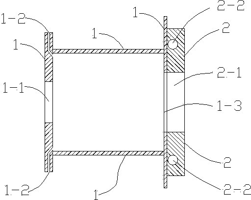
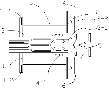
[0026] Embodiment 1: the inductively coupled plasma ion source gas protection device of this embodiment, such as figure 1 As shown, a hollow gas shield body 1 is included, and its material is polytetrafluoroethylene. The gas shield body 1 is cylindrical, and the end face of one end of the gas shield body 1 is provided with a torch tube for installing a plasma torch tube 3 Hole 1-1, the size of torch tube hole 1-1 is suitable with plasma torch tube 3 sizes, as image 3 As shown, the gas shield 1 wraps part of the plasma torch 3 and the coil 4 of the high-frequency generator. There are two air inlets 1-2, the air inlet passages are curved, and the inner openings of the air inlets 1-2 face the direction of the tangent line of the torch hole 1-1.

[0027] An opening 1-3 communicating with the outside is made at the other end of the gas shielding cover 1, and the opening 1-3 is opposite to the inductively coupled plasma interface device 5, and a water cooling device 2 is installed...

Embodiment 2

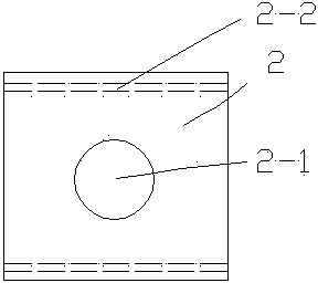
[0029] Embodiment 2: the inductively coupled plasma ion source gas protection device of this embodiment, such as Figure 4 , 5 As shown, the copper block of the water cooling device 2 is made into a circle, and one end of the copper block is formed with a protruding convex step to facilitate rotation, and an external thread is formed around the copper block, and the opening 1-3 of the gas shielding cover body 1 Corresponding internal threaded holes 1-4 are formed at corresponding positions, so that the copper block is threadedly connected with the gas shielding case 1, so that the case can adjust the size of the gap 6 for different plasma torches 3-1. Other technical characteristics are consistent with embodiment 1.

[0030] When using the device, adjust the gap distance between the device and the inductively coupled plasma interface device 5, then pass argon gas into the gas shielding cover 1 at a rate of 0.3 L / min, and connect the external cooling water of the water cooling...


PUM


Abstract

The invention relates to an inductively coupled plasma ion source gas protection method and an inductively coupled plasma ion source gas protection device. The inductively coupled plasma ion source gas protection device provided by the invention comprises a hollow gas shielding case body, wherein one end of the gas shielding case body is provided with a torch tube hole corresponding to a plasma torch tube and a gas inlet, and the other end of the gas shielding case body is provided with an opening communicated with the outside; the opening is against an inductively coupled plasma interface device; a water cooling device is arranged at the opening, and is in fit with the inductively coupled plasma interface device to form the gas outlet end of the gas shielding case body; and the gas outlet end of the gas shielding case body is communicated with the outside. By the inductively coupled plasma ion source gas protection method and the inductively coupled plasma ion source gas protection device provided by the invention, inductively coupled plasmas (ICP) are positioned in an inert gas atmosphere to radically eliminate or reduce interference formed by O, N, H, C and the like, reduce background equivalent concentration and improve a linear correlation coefficient and a detection limit.

Description

technical field [0001] The invention relates to an inductively coupled plasma device, in particular to an inductively coupled plasma ion source gas protection device used in an inductively coupled plasma mass spectrometer. Background technique [0002] Inductively coupled plasma mass spectrometry (ICP-MS) is an element and isotope analysis technique developed in the 1980s that uses inductively coupled plasma (ICP) as an ion source and generally uses a quadrupole as a mass analyzer. ICP-MS can perform qualitative analysis, semi-quantitative analysis, quantitative analysis, isotope ratio analysis, and element speciation analysis combined with separation techniques. [0003] The inductively coupled plasma device consists of a plasma torch and an induction coil connected to a high-frequency generator. A plasma torch consisting of three concentric quartz tubes is placed inside the induction coil. When argon gas is introduced, if a high-voltage spark is used to ionize part of th...

Claims


Application Information

Patent Timeline
Patent Type & Authority Patents(China)
IPC IPC(8): H01J49/10
CPCH01J49/105
Inventor 金献忠陈建国杨文潮杭纬李灵锋
Owner NINGBO ACAD OF SCI & TECH FOR INSPECTION & QUARANTINE
Why Eureka
Try Eureka