Thermal radiation heat dissipation thin film structure and manufacturing method thereof

A heat-dissipating film and its manufacturing method technology, applied in the direction of chemical instruments and methods, heat exchange equipment, heat exchange materials, etc., can solve the problems of loss, high LED, bulky end products, etc.

Inactive Publication Date: 2011-11-30
JINGDEZHEN FARED TECH
View PDF4 Cites 8 Cited by
  • Summary
  • Abstract
  • Description
  • Claims
  • Application Information

AI Technical Summary

Problems solved by technology

[0005] However, the disadvantage of the heat conduction mechanism of the above-mentioned prior art is that the heat is transmitted from high temperature to low temperature, and it is proportional to the area, so the surface area of ​​the heat sink needs to be greatly increased, resulting in increased material costs, and making the end product too bulky and inconvenient use
Taking LED light bulbs as an example, the price can be more than ten times that of ordinary light bulbs, so it loses the incentive for ordinary people to use them
In addition, when the temperature of the 2W LED reaches 135°C, the temperature can be reduced to about 125°C or 115°C by the connected heat sink, but it is still too high for the LED

Method used


Image

  • Thermal radiation heat dissipation thin film structure and manufacturing method thereof
  • Thermal radiation heat dissipation thin film structure and manufacturing method thereof
  • Thermal radiation heat dissipation thin film structure and manufacturing method thereof

Examples


Embodiment Construction

[0013] The implementation of the present invention will be described in more detail below in conjunction with the accompanying drawings, so that those skilled in the art can implement it after studying this specification.

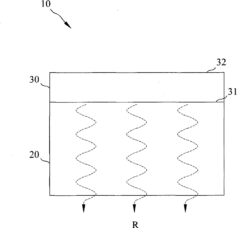
[0014] refer to figure 1 , is a schematic diagram of the structure of the thermal radiation heat dissipation film of the present invention. Such as figure 1 As shown, the heat radiation heat dissipation film structure 10 of the present invention includes a substrate 20 and a heat radiation heat dissipation film 30, wherein the substrate 20 is electrically insulating and has a first coefficient of thermal expansion, and the heat radiation heat dissipation film 30 is formed on the substrate 20, and It has the second coefficient of thermal expansion, especially the difference ratio between the first coefficient of thermal expansion of the substrate 20 and the second coefficient of thermal expansion of the heat radiation heat dissipation film 30 is not greater...


PUM


Abstract

The invention discloses a thermal radiation radiating film structure and a manufacturing method thereof. The thermal radiation radiating film structure comprises a substrate and a thermal radiation radiating film, wherein the thermal radiation radiating film is formed on the substrate; the substrate has electric insulation property; a difference ratio of thermal expansion coefficients of the substrate and the thermal radiation radiating film is not more than 0.1%; the thermal radiation radiating film is composed of a crystal containing metal and nonmetal and has a surface microstructure; and the thermal radiation radiating film is formed in the way that a composite containing required metal and nonmetal is coated on a heated substrate in the manner of high-pressure coating. The thermal radiation radiating film can be used for transferring heat in the thermal radiation manner along the direction toward the substrate, thereby greatly improving the radiating efficiency so that the temperature of an external object outside the substrate can be not lower than the temperature of the thermal radiation radiating film.

Description

technical field [0001] The invention relates to a thermal radiation heat dissipation thin film structure and a manufacturing method thereof, in particular to a thin film structure capable of heat dissipation with high efficiency in a thermal radiation manner and a manufacturing method thereof. Background technique [0002] Regardless of whether it is a mechanical component or an electrical device, excessive operating temperature often leads to poor function or even failure, and also shortens the service life. Therefore, different heat dissipation devices or mechanisms are required to avoid operating temperatures above the critical value. [0003] Take an internal combustion engine as an example. Gasoline or diesel is compressed at high pressure in the engine and then ignited to produce an explosion and output power to drive the gear set or transmission mechanism to move the vehicle. Due to the extremely high operating temperature inside the engine, if there is no proper heat...

Claims


Application Information

Patent Timeline
Patent Type & Authority Applications(China)
IPC IPC(8): H01L23/373H01L33/64H05K7/20C09K5/14
CPCH01L21/4871F28F2245/06H01L23/367H01L23/3735F28F21/08H01L33/641H01L23/3736H01L2924/0002H01L2924/00
Inventor 陈烱勋
Owner JINGDEZHEN FARED TECH
Why Eureka
Try Eureka