Flat tube heat exchanger and its assembly method

An assembly method and heat exchanger technology, which is applied in lighting and heating equipment, evaporator/condenser, refrigeration components, etc., can solve the problems of large insertion stroke, large influence of fin flanging, and difficult determination of fin spacing , to achieve the effect of solving interference, reducing welding difficulty and improving product quality

Inactive Publication Date: 2011-12-07
LG ELECTRONICS (TIANJIN) APPLIANCES CO LTD
View PDF5 Cites 12 Cited by
  • Summary
  • Abstract
  • Description
  • Claims
  • Application Information

AI Technical Summary

Problems solved by technology

[0006] In the prior art, when assembling, the fins are stacked first, and then the flat tubes are inserted vertically for assembly; the insertion stroke of the flat tubes from the lower end to the top of the fins is relatively large, which has a great influence on the flanging of the fins, resulting in It is difficult to determine the spacing of the fins, which will adversely affect the fit between the fins and the flat tubes and reduce the heat dissipation efficiency of the heat exchanger;
[0007] Moreover, in the assembly process, the welding between the flat tube and the fin is soldering, and the welding between the flat tube and the header is brazing. After the soldering is completed, the brazing is performed, which is easy to affect The quality of soldering will cause the fins to be fixed unstable, which will affect the heat dissipation and drag coefficient

Method used


Image

  • Flat tube heat exchanger and its assembly method
  • Flat tube heat exchanger and its assembly method
  • Flat tube heat exchanger and its assembly method

Examples


Embodiment Construction

[0022] Below in conjunction with accompanying drawing and specific embodiment the present invention is described in further detail:

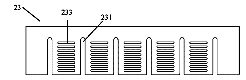
[0023] Such as image 3 As shown, the fin 23 is a rectangular aluminum sheet, on which a plurality of groups of punching holes 233 are evenly spaced, and the punching holes 233 are set along the length direction of the rectangular fin, and the punching holes 233 are conducive to the air flow inside. Circulation to enhance the heat dissipation effect of the radiator. Between the two groups of punching holes 233, there is a "U"-shaped pipe groove 231, and the openings of the pipe groove 231 are all arranged on the same side of the fin 23, wherein the width of the pipe groove 231 is slightly larger than that described below. The thickness of the flat tube 22 is generally 1-10 mm larger than that of the flat tube 22 , that is, the flat tube 22 can smoothly enter the pipe groove 231 .

[0024] Further, the open end of the pipe groove is formed with...


PUM


Abstract

The invention provides an assembly method of a flat tube heat exchanger. The assembly method comprises the following steps: (1) firstly brazing a collecting tube and a flat tube of the heat exchanger at a high temperature to form a heat exchanger framework; (2) arranging a welding material on the surface of the flat tube of the heat exchanger framework; (3) sequentially and alternately fixing fins in a fixed groove of a fixed station regularly, and arranging the opening end of a U-shaped pipe groove outwards; (4) allowing the fixed station to get close to the heat exchanger framework so that the flat tube is correspondingly inserted into a fin pipe groove until the flat tube enters the bottom of the pipe groove; and (5) placing the assembled heat exchanger in a low-temperature brazing furnace for soft soldering so as to complete connection assembly of the heat exchanger. In the assembly method, firstly the flat tube and the collecting tube are welded into the heat exchanger framework and then the fins are assembled, which can well eliminate interference in combination of soft soldering and hard soldering and prevent soft solder from being refused to affect the heat transfer coefficient during the hard soldering process; and meanwhile the welding difficulty of the flat tube and the collecting tube is reduced, and the product quality is improved.

Description

technical field [0001] The invention relates to a flat tube heat exchanger, in particular to a flat tube heat exchanger and an assembly method thereof. Background technique [0002] When the room air conditioner is running in cooling mode, the indoor air flows through the evaporator to reduce the temperature. At the same time, because the temperature of the surface of the evaporator is generally significantly lower than the dew point temperature of the air, when the air flows through the surface of the evaporator, part of the moisture in the air will be precipitated, thereby forming condensed water on the surface of the evaporator. The condensed water on the surface of the evaporator should be drained in time. If the condensed water accumulates on the surface of the evaporator, it will block the air flow channel, increase the flow resistance of the air, and reduce the efficiency of the evaporator: water droplets may also blow into Indoor conditions lead to substandard quali...

Claims


Application Information

Patent Timeline
Patent Type & Authority Applications(China)
IPC IPC(8): B23K1/00B23K1/20F25B39/00
Inventor 车金峰崔静
Owner LG ELECTRONICS (TIANJIN) APPLIANCES CO LTD
Why Eureka
Try Eureka