Engine intake pipe water injection system

A technology of water spray system and air intake pipe, which is applied to engine components, machines/engines, charging systems, etc., can solve the problems of complex structure, unsolvable problems of water emulsion fuel phase separation, poor economy, etc., and achieves high control accuracy. Effect

Inactive Publication Date: 2011-12-07
TIANJIN UNIV
View PDF9 Cites 20 Cited by
  • Summary
  • Abstract
  • Description
  • Claims
  • Application Information

AI Technical Summary

Problems solved by technology

But its disadvantages are: 1. The phase separation problem of water emulsified fuel has not been solved, and the emulsified fuel is prone to problems such as turbidity and demulsification as the storage time goes by
2. The cost of emulsifier is high, and the economy of large-scale use is poor
3. Water-emulsion fuel is corrosive to the engine fuel supply system and oil supply system, and it will cause poor lubrication of high-pressure oil pump or injector needle valve when burning high-ratio water-emulsion fuel
4. The incorporation of water will occupy the original fuel channel and affect the power density of the engine
But its disadvantages are: 1. It is very difficult to change the engine structure, and the requirements for water spray equipment are very high. It is still necessary to add a system similar to the engine electronic control unit, the structure is complex, and the cost is too high
But the disadvantages are: 1. If the water atomization and combustion temperature are not well controlled, the effect will be poor
2. If the optimization is not good, it may affect the intake of the engine

Method used


Image

  • Engine intake pipe water injection system
  • Engine intake pipe water injection system

Examples


Embodiment Construction

[0013] The present invention will be described in further detail below in conjunction with the accompanying drawings and examples. The following examples are only descriptive, not restrictive, and cannot limit the protection scope of the present invention with this.

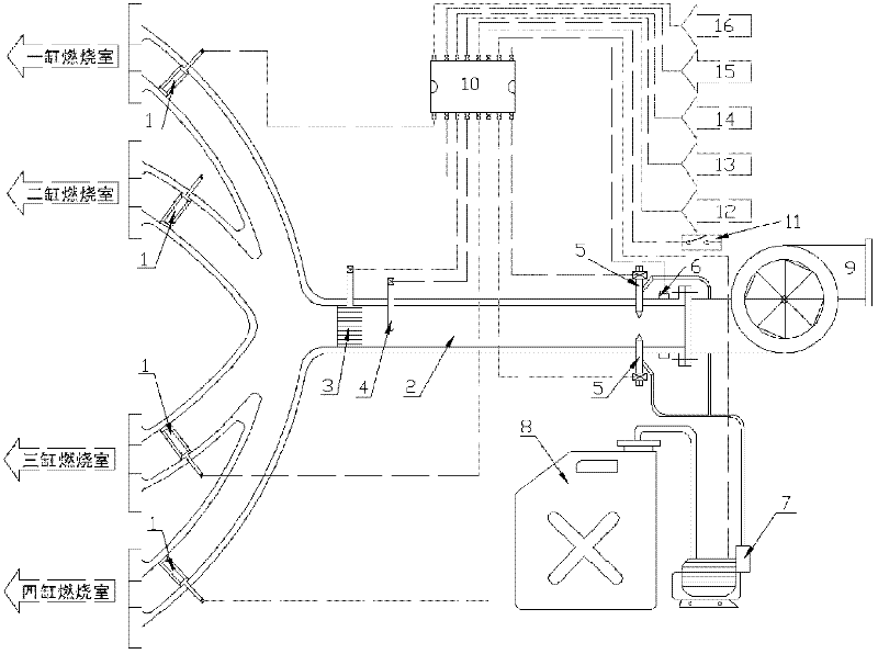
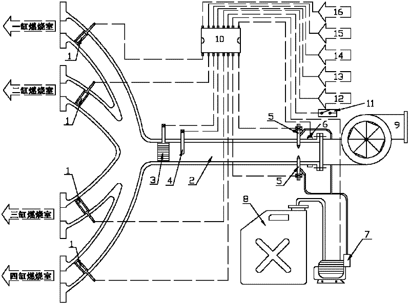
[0014] The system connection of the present invention is as follows: each intake manifold leading to the combustion chamber is provided with a convex evaporation zone 1, and the intake manifold 2 is sequentially provided with a grid type droplet evaporator 3, an intake air temperature sensor 4, an electromagnetic A high-pressure water atomizing nozzle 5 and an air intake flow sensor 6; the electromagnetic high-pressure water atomizing nozzle 5 is connected in series with a high-pressure water pump 7 and a water storage tank 8; The main control chip 10 in the water spray electronic control subsystem of the intake pipe is respectively connected to: the electromagnetic high-pressure water atomization nozzle 5, the in...


PUM


Abstract

The invention discloses an air intake tube water spray system of an engine. Each intake manifold leading to a combustion chamber is internally provided with a convex evaporation belt; an air intake duct general pipe is sequentially provided with a grate-type liquid drop evaporator, an air intake temperature sensor, an electromagnetic high-pressure water atomizing nozzle and an air intake flow rate sensor; the electromagnetic high-pressure water atomizing nozzle is sequentially connected with a high-pressure water pump and a water storage pump in series; an inlet end of the air intake duct general pipe is provided with a gas compressor; and a main control chip in an air intake pipe water spray electric control subsystem is respectively connected to the components above through a light beam, as well as is connected to a manual / automatic water spray water exchange switch, a cooling water temperature sensor, a power sensor, a fuel oil consumption sensor, an exhaust temperature sensor, a rotation speed sensor and the like. The intake air is ensured to have favorable water atomization under the condition of no improvement of air intake temperature as far as possible to achieve the optimal temperature control effect; and the system provided by the invention can be controlled full-automatically and exchanged manually, the system is easy to modify on the existing engine, and the control accuracy is high, and the air intake pipe water spray strategy can be regulated appropriately as the working conditions of the engine.

Description

technical field [0001] The invention belongs to the structure of an internal combustion engine, and in particular relates to a water spray system for an engine intake pipeline. Background technique [0002] In recent years, the standards for the emission limits of vehicle exhaust pollutants have been continuously improved, and countries have competed to carry out research on reducing nitrogen oxides and soot emission control technologies. These include the research on the method of mixing water in the combustion chamber to reduce the combustion temperature, such as water emulsified fuel, water injection in the combustion chamber, water injection in the intake pipe, etc. Experiments have shown that for some high-load engine conditions, proper mixing of water in the combustion chamber can effectively absorb the heat in the cylinder and reduce the combustion temperature. At the same time, water vapor can dilute the locally over-concentrated oxygen. High temperature and high ox...

Claims


Application Information

Patent Timeline
Patent Type & Authority Applications(China)
IPC IPC(8): F02M25/028
Inventor 舒歌群张韦徐彪梁兴雨卫海桥
Owner TIANJIN UNIV
Why Eureka
Try Eureka