Optical absorbance measurement with self-calibration and extended dynamic range

An absorbance, target range technique applied in the field of optical absorbance measurement

Active Publication Date: 2011-12-07
ENDRESS + HAUSER OPTICAL ANALYSIS INC
View PDF6 Cites 5 Cited by
  • Summary
  • Abstract
  • Description
  • Claims
  • Application Information

AI Technical Summary

Problems solved by technology

However, each of the above techniques includes limitations that make them less suitable for providing optical measurement accuracy and / or precision over a wide dynamic range

Method used


Image

  • Optical absorbance measurement with self-calibration and extended dynamic range
  • Optical absorbance measurement with self-calibration and extended dynamic range
  • Optical absorbance measurement with self-calibration and extended dynamic range

Examples


Embodiment Construction

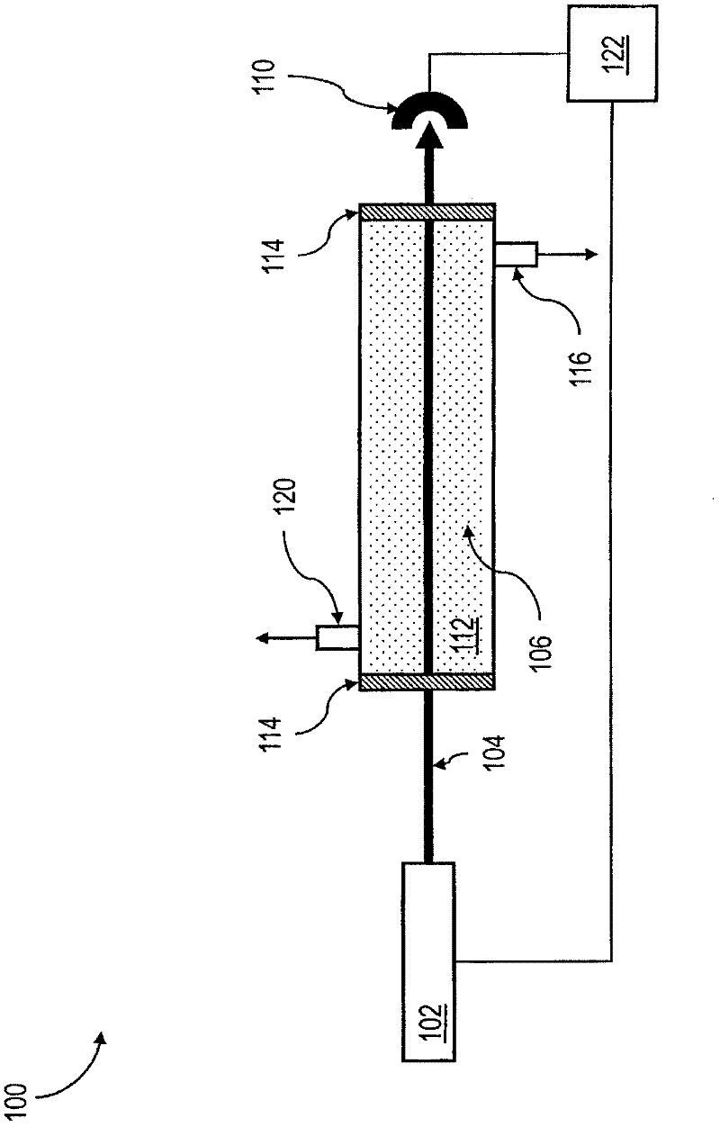
[0020] Such as figure 1 As shown, system 100 may include a light source 102 operating at a wavelength of interest that provides a continuous beam or pulses of light 104 that passes through a volume 106 of a sample gas before being detected by a detector 110 . The light source 102 may include one or more lasers, such as a tunable diode laser (TDL), a quantum cascade laser (QCL), a horizontal cavity laser, a vertical cavity surface emitting semiconductor laser (VCSEL), or other similar lasers for tunable light. Devices where non-linear frequencies occur. Detector 110 may include one or more photodiodes, photodetectors, or photoacoustic detectors. In some embodiments, a sample gas of volume 106 may be contained in a sample cell 112 having one or more windows 114 through which light 104 in continuous or pulsed form enters and exits volume 106 . The sample chamber 112 can be as figure 1 A flow through cell is shown in which gas flows into the sample cell 112 through the inlet 11...


PUM


Abstract

Detector data representative of an intensity of light that impinges on a detector after being emitted from a light source and passing through a gas over a path length can be analyzed using a first analysis method to obtain a first calculation of an analyte concentration in the volume of gas and a second analysis method to obtain a second calculation of the analyte concentration. The second calculation can be promoted as the analyte concentration upon determining that the analyte concentration is out of a first target range for the first analysis method.

Description

[0001] Cross References to Related Applications [0002] This application claims U.S. Provisional Patent Application No. 61 / 186,749, filed June 12, 2009, entitled "Online Self-Calibrating Optical Absorption Sensors with Expanded Dynamic Range" rights, the entire contents of the case are incorporated herein by reference. technical field [0003] In general, the subject matter described herein relates to optical absorptivity measurements, and more specifically, it relates to embodiments that provide self-calibration capabilities and extended dynamic measurement ranges for optical absorption sensors. Background technique [0004] Various spectroscopic techniques have proven and continue to be used for trace gas detection using a variety of light sources. Two absorption spectroscopy techniques that can be used for this measurement are direct absorption spectroscopy and modulation spectroscopy. Although somewhat different in principle, both techniques can be used to measure imp...

Claims


Application Information

Patent Timeline
Patent Type & Authority Applications(China)
IPC IPC(8): G01J3/42G01N21/25
CPCG01N21/3554G01N21/39G01N21/3504G01N2021/399G01N21/05G01J3/433G01N21/274G01J3/02G01J3/42G01J3/4338G01J2003/4332G01J2003/4334G01N21/031G01N2021/354
Inventor 刘翔A·法伊蒂施X·周
Owner ENDRESS + HAUSER OPTICAL ANALYSIS INC
Why Eureka
Try Eureka