Anaerobic-aerobic integrated microbial fuel cell wastewater treatment system

A sewage treatment system, fuel cell technology, applied in the field of environmental protection and resource integration - water pollution prevention and control

Active Publication Date: 2011-12-14
BEIJING NORMAL UNIVERSITY
View PDF7 Cites 20 Cited by
  • Summary
  • Abstract
  • Description
  • Claims
  • Application Information

AI Technical Summary

Problems solved by technology

Invention patent (CN1364146A) proposes a biofuel cell using wastewater and activated sludge for wastewater treatment. It uses a double-chamber fuel cell and uses septic tank wastewater and

Method used


Image

  • Anaerobic-aerobic integrated microbial fuel cell wastewater treatment system
  • Anaerobic-aerobic integrated microbial fuel cell wastewater treatment system
  • Anaerobic-aerobic integrated microbial fuel cell wastewater treatment system

Examples


Embodiment 1

[0028] Example 1 Anaerobic-aerobic integrated microbial fuel cell treatment of wastewater containing refractory organic matter

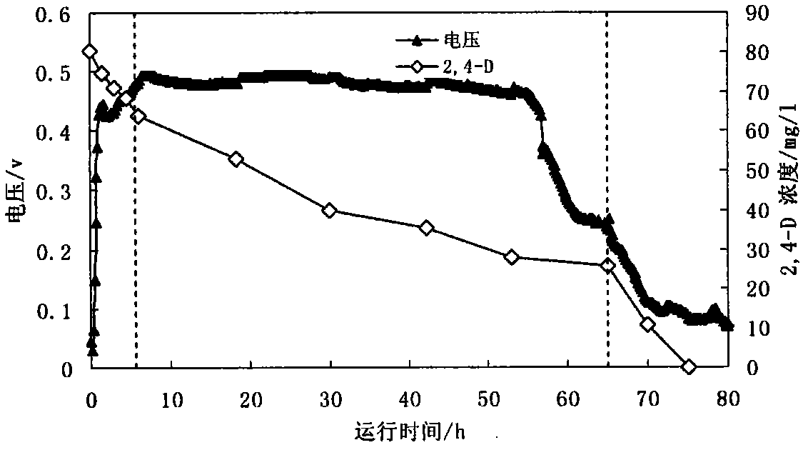
[0029] A high-concentration organic wastewater contains a certain amount of refractory organic matter 2,4-dichlorophenoxyacetic acid as the target substance (2,4-D for short). The activity is inhibited, and the simple anaerobic power generation operation mode is difficult to degrade the 2,4-D in the organic wastewater. The anaerobic-aerobic integrated microbial fuel cell system can effectively remove 2,4-D at the same time Ensure good power production efficiency. The specific implementation steps are as follows:

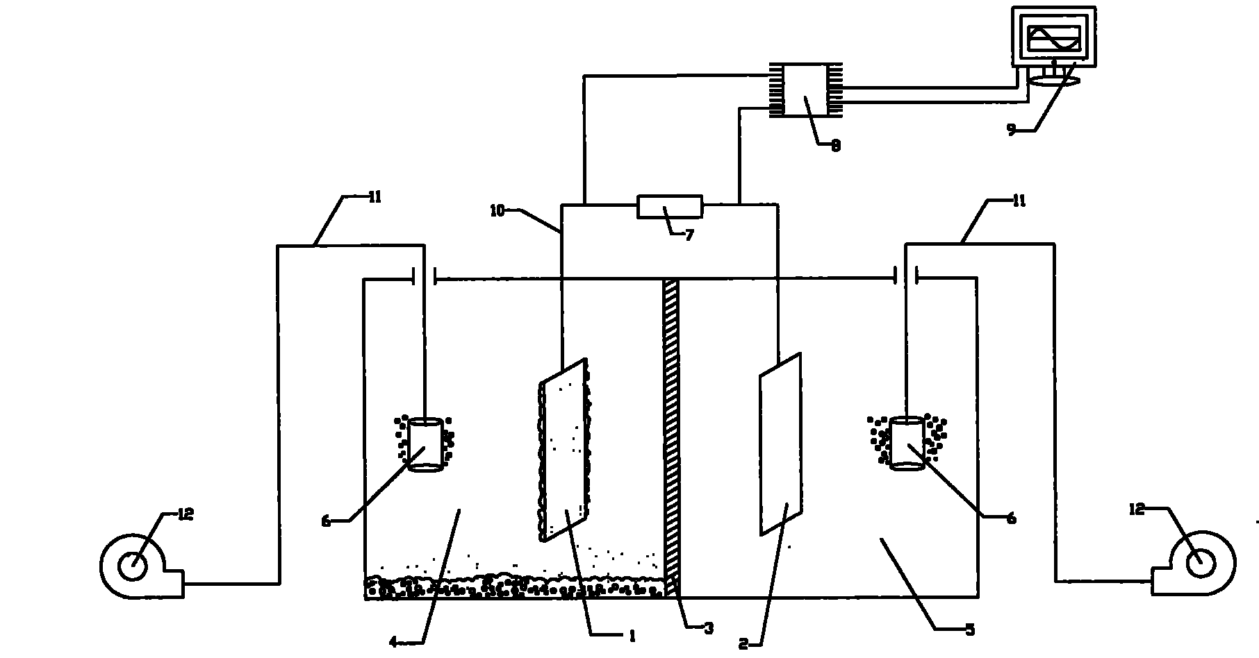
[0030] (1) Microbial fuel cell system construction: a dual-chamber microbial fuel cell is used, and its specific structure is shown in figure 1 , it includes a cathode chamber, an anode chamber, an anode is inserted into the anode chamber, a cathode is inserted into the cathode chamber, the anode is made of carbon felt, the cathode is mad...

Embodiment 2

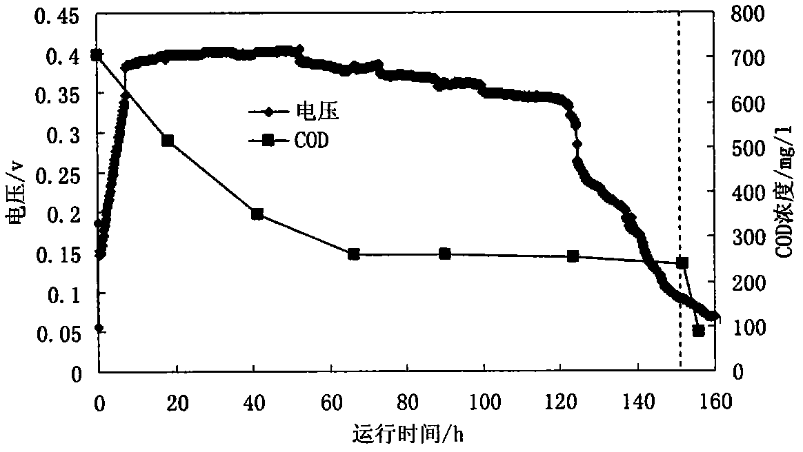
[0034] Example 2 Anaerobic-aerobic integrated microbial fuel cell treatment of certain high-concentration organic wastewater

[0035] (1) Microbial fuel cell system construction: a dual-chamber microbial fuel cell is used, and its specific structure is shown in figure 1 , including it includes a cathode chamber, an anode chamber, an anode is inserted into the anode chamber, a cathode is inserted into the cathode chamber, the anode is made of carbon cloth, the cathode is made of platinum-loaded carbon cloth, the cathode chamber and the anode chamber are separated by a proton exchange membrane, and the anode and cathode are separated by a proton exchange membrane. Connect the wire to the external resistor, and connect the load resistor to the data acquisition device.

[0036] (2) Enrichment and cultivation of facultative electricity-producing microorganisms at the anode of microbial fuel cells: use sodium acetate as an easily degradable carbon source to enrich and cultivate the ...


PUM


Abstract

The invention relates to an anaerobic-aerobic integrated microbial fuel cell wastewater treatment system. Facultative power-generating bacteria and facultative degrading bacteria are constructed in an anode chamber of a microbial fuel cell and the alternate anaerobic-aerobic operation mode is adopted, thus the aim of utilizing the anaerobic power generation of the organic matter and realizing aerobic degradation can be achieved. By adopting the system, the problem that when the past microbial fuel cell system utilizes organic wastewater to generate power, the degradation of the organic matter is not complete, can be overcome and the resource utilization and harmless emission of organic wastewater can be realized. The system has the following specific characteristics: the fuel cell system comprises a cathode chamber, the anode chamber, an anode in the anode chamber, a cathode in the cathode chamber, a diaphragm between the cathode and the anode and aeration headers arranged in the cathode chamber and the anode chamber; the facultative power-generating microorganisms are attached to the anode of the anode chamber, the facultative degrading microorganisms exist in the solution of the anode chamber; and the alternate anaerobic-aerobic operation mode is adopted to realize wastewater power generation under the anaerobic condition and the rapid degradation of the organic matter under the aerobic condition.

Description

Technical field [0001] The invention relates to an anaerobic-aerobic integrated microbial fuel cell wastewater treatment system, which belongs to the field of environmental protection and resource integration-water pollution prevention and control. Background of the invention [0002] In recent years, with the development of the global energy crisis and the advancement of fuel cell technology, the use of electrochemically active microorganisms (electricity-producing microorganisms) for pollution control and energy recovery has increasingly attracted the attention of researchers at home and abroad (Rabaey et al., 2005 ; Logan et al., 2006; Lovley, 2006). The typical characteristic of electrochemically active microorganisms is that they can metabolize organic matter while transferring electrons from the inside to the outside of the cell, and recover electrical energy by forming a closed circuit with the help of electrodes and wires. Microbial fuel cell (MFC) is currently the ...

Claims


Application Information

Patent Timeline
IPC IPC(8): C02F3/30C02F3/34H01M8/16
CPCY02E60/527Y02E60/50
Inventor 全向春全燕苹杨志峰
Owner BEIJING NORMAL UNIVERSITY
Why Eureka
Try Eureka