Self-supplementing gas energy dissipation method and device in cave
A technology of energy dissipation device and flood discharge tunnel, which is applied in water conservancy engineering, marine engineering, coastline protection and other directions, can solve the problems of large amount of ventilation wells, difficult construction, damage to the ecological environment, etc., to achieve stable water flow, increase construction difficulty, engineering volume reduction effect
- Summary
- Abstract
- Description
- Claims
- Application Information
AI Technical Summary
Problems solved by technology
Method used
Image
Examples
Embodiment 1
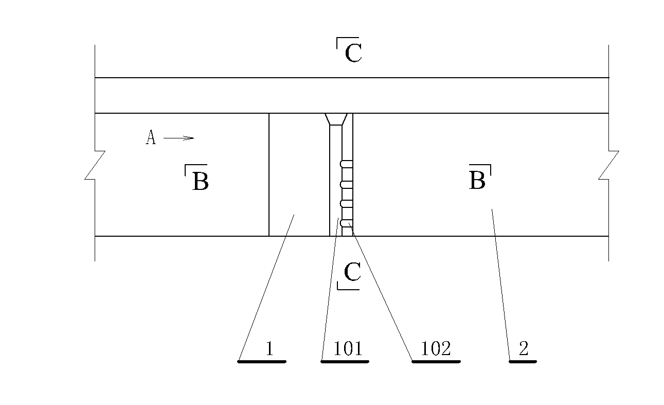
[0038] This embodiment is a self-supplementing energy dissipation device in a cave, such as figure 1 shown. This embodiment includes: the entrance of the flood discharge tunnel, the entrance of the flood discharge tunnel is connected to the top of the connecting well, the bottom of the connecting well is connected to the water outlet tunnel rebuilt from the gate-shaped diversion tunnel, and the inlet section in the water outlet tunnel A water-blocking pier is provided, and the water-blocking pier is provided with a ventilation pipe that can guide the air-water mixed flow at the top of the water outlet hole to the water surface behind the water-blocking pier. When the water flow passes through the connecting well, a large amount of air will be carried, or a large amount of air will be mixed in the water to prepare for the energy dissipation of the water blocking pier in the outlet tunnel.
[0039] The connection well described in this embodiment is a transitional section conne...
Embodiment 2
[0047] This embodiment is the improvement of the first embodiment, and it is the refinement of the first embodiment about the water blocking pier. The water-blocking pier described in this embodiment is one of a raised ridge, a side pier, a pressing plate, a composite pier and a dispersed composite pier.
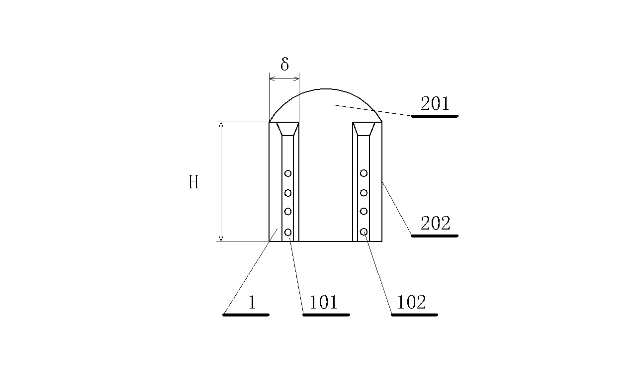
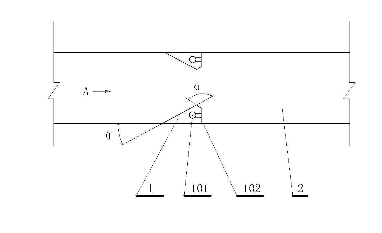
[0048] The structure of the pier see figure 1 , 2 , 3, in the figure A is the flow direction. The side pier 1 described in this embodiment is a general term for two water blocking piers symmetrically arranged on the two side walls of the water outlet hole 2 . Usually, side piers appear in pairs. The shape of the horizontal section of the side pier (section parallel to the horizontal plane) is approximately triangular, such as image 3 shown. In appearance, it looks like two symmetrical vertical piers on both sides of the water outlet (such as figure 2 ), using the sudden expansion of the side pier outlet to dissipate energy. The included angle θ=(20°~30°) between the...
Embodiment 3
[0055] This embodiment is an improvement of Embodiment 1, and it is a refinement of Embodiment 1 about the connecting well and the water blocking pier. The connecting well described in this embodiment is an open flow inclined well, and the described water blocking pier is an open The upstream side pier at the front end of the reverse arc section of the flow-inclined well, the ridge at the rear end of the reverse-arc section of the flow-inclined well, and the downstream side pier arranged downstream of the ridge.
[0056] This embodiment is an improvement on the arrangement of aeration tanks under traditional inclined shafts, and is a refinement of Embodiment 1 on connecting wells and corresponding water cushion ponds (that is, the submerged water cushion formed upstream of the water blocking pier in the water outlet tunnel), such as Figure 15 shown. The connection well 802 described in this embodiment is an open flow inclined well, and the water cushion pond refers to the sub...
PUM
 Abstract
Description
Claims
Application Information
 - R&D
- Intellectual Property
- Life Sciences
- Materials
- Tech Scout
- Unparalleled Data Quality
- Higher Quality Content
- 60% Fewer Hallucinations
Browse by: Latest US Patents, China's latest patents, Technical Efficacy Thesaurus, Application Domain, Technology Topic, Popular Technical Reports.
© 2025 PatSnap. All rights reserved.Legal|Privacy policy|Modern Slavery Act Transparency Statement|Sitemap|About US| Contact US: help@patsnap.com


