Top beam connector

A technology for connecting pieces and roof beams, applied in the direction of construction and building structure, can solve the problems of large waste of building materials, increase the difficulty of installation, and reduce the efficiency of installation, so as to reduce construction waste, reduce labor intensity, and save installation time. Effect

Inactive Publication Date: 2011-12-14
杨东佐
View PDF8 Cites 9 Cited by
  • Summary
  • Abstract
  • Description
  • Claims
  • Application Information

AI Technical Summary

Problems solved by technology

[0002] Existing cement-brick, reinforced-concrete house building and construction method thereof, owing to need to draw frame, cast concrete etc. with steel bar at the construction site, there is following shortcoming: the one is that its top beam is poured and built earlier, and then the top beam Concrete floor slabs are built with top pouring. The connection between the cement floor slab and the roof beam mainly depends on the steel bars on the roof beam and the cement floor slab. Since the roof beam and the cement floor slab are constructed in two pours, the construction period is long, the labor intensity is high, and the pollution Large, noisy, and waste of construction raw materials; second, the relationship between two cement solids is only the bearing relationship of mechanical loads, and it is impossible to establish a truly integrated internal relationship, which has poor safety, poor seismic performance, and short service life; It is necessary to use building materials such as cement and wood, which destroys the ecology; the fourth is that when the house is demolished, the building materials cannot be reused, resulting in a waste of resources and a large amount of construction waste that is difficult to deal with; the fourth is that the frame structure of traditional cement buildings (high-rise buildings) The self-weight is very heavy, and the mechanical load of the foundation is very large. Once the earthquake shakes, the whole building will become very fragile, very dangerous, and very unfavorable for earthquake resistance
Second, there are many bolts and other fastening connections or welding connections on site, which will increase the difficulty of installation, reduce installation efficiency, and result in high labor and time costs for on-site construction.
The third is that the traditional building steel structure frame beams and columns or beams and beams are connected by bolt fastening or welding, and the respective connection ends must be designed and processed for matching connections. When standard profiles are used for beams or columns , the connecting ends must be designed and processed separately. When beams or columns do not use standard profiles, they need to be specially manufactured. Bot...

Method used


Image

  • Top beam connector
  • Top beam connector
  • Top beam connector

Examples


Embodiment 1

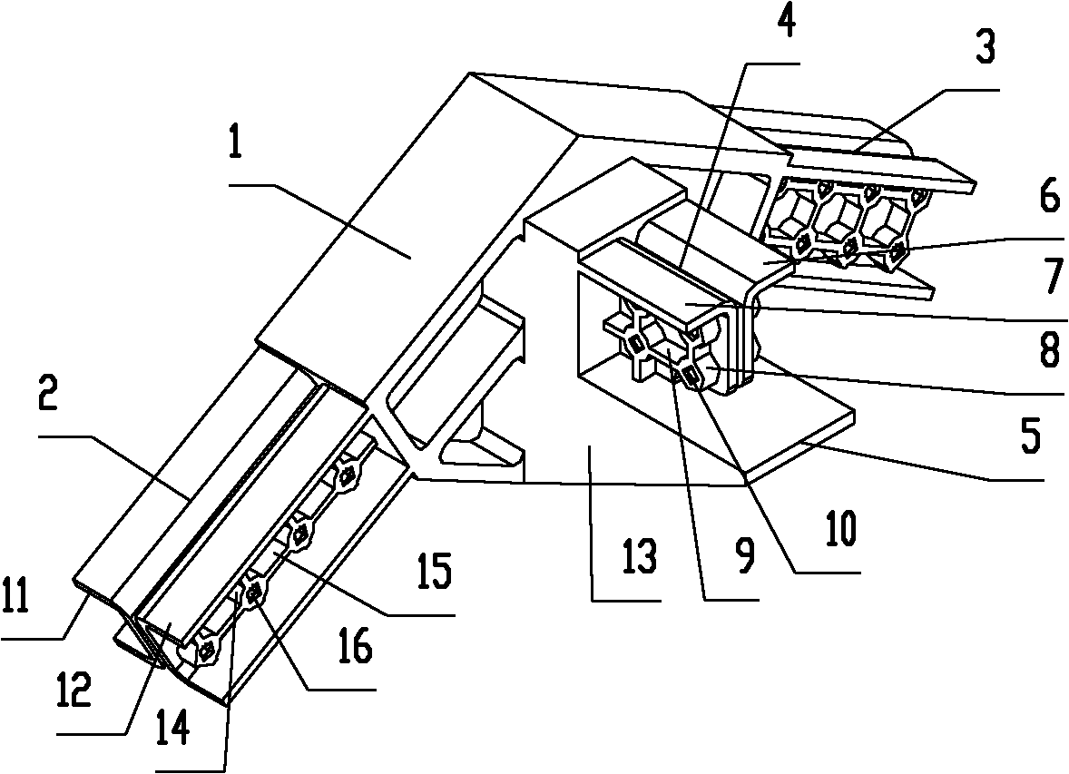
[0038] Such as figure 1 As shown, the roof beam connector includes the roof beam connector body 1, and the roof beam connector body 1 protrudes obliquely downward from the opposite sides of the beam-column connector body, and the roof beam oblique insertion joint with an inverted V-shaped structure and symmetry 2. The top beam oblique insertion joint 3 is a horizontal support joint 4 protruding horizontally from one side of the top beam connector body 1 .

[0039] The horizontal support joint 4 includes a side protrusion 5 protruding from one side of the top beam connector body 1, two side-by-side limiting protrusions 6 extending vertically upward from the top surface of the side protrusion 5 and then bending outwards, The gap between the position-limiting protrusion 7, the position-limiting protrusion 6 and the position-limiting protrusion 7 forms an accommodating groove for accommodating the vertical portion of the end of the beam whose end is processed into a T-shape. On t...

Embodiment 2

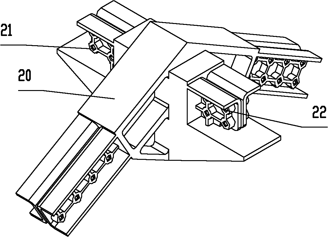
[0042] Such as figure 2 As shown, the difference from Embodiment 1 is that the horizontal support joint includes structurally symmetrical horizontal support joints 21 and 22 protruding horizontally from the two opposite sides of the top beam connector body 20 .

Embodiment 3

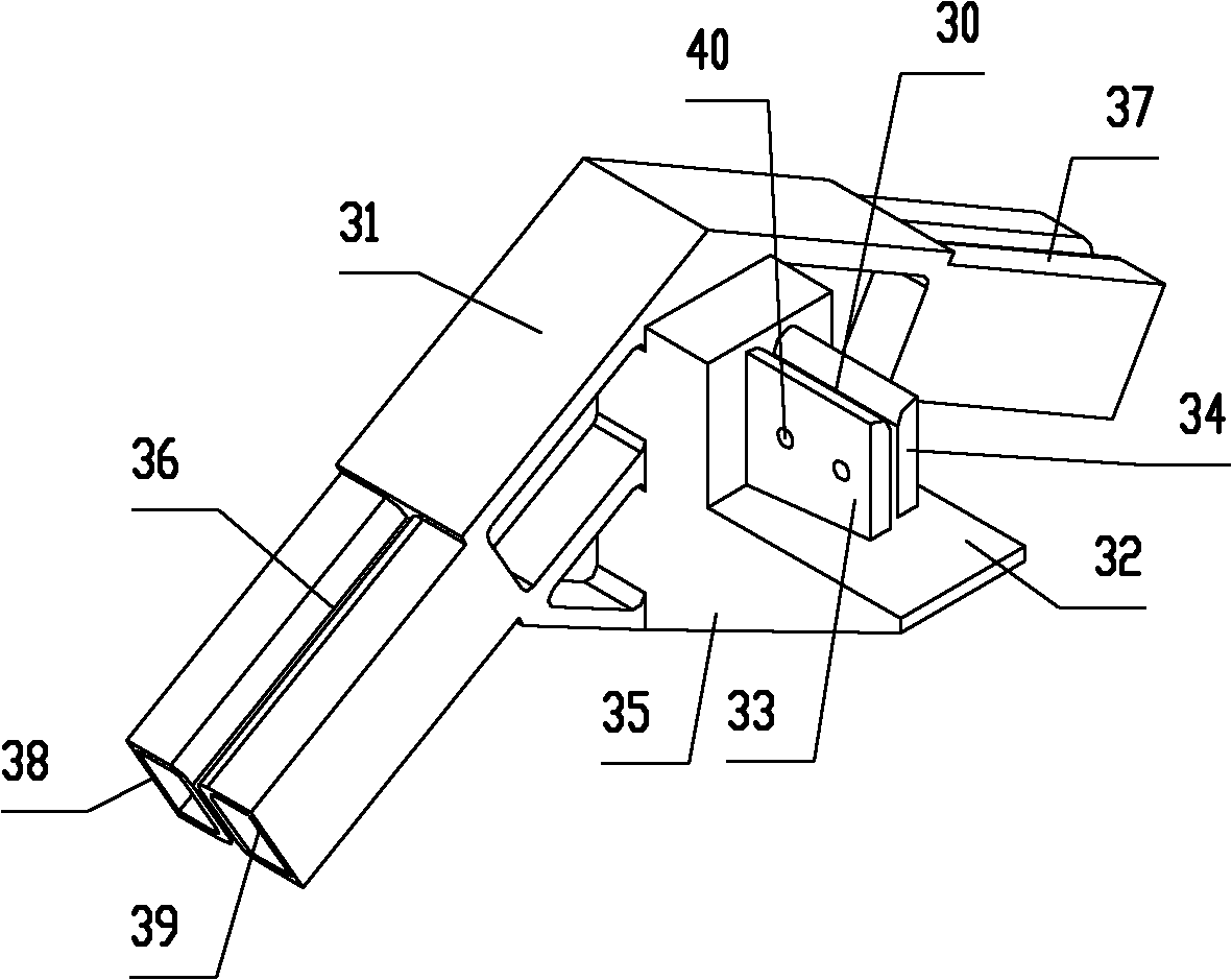
[0044] Such as image 3 As shown, the difference from Embodiment 1 is that the horizontal support joint 30 includes a side protrusion 32 protruding from one side of the top beam connector body 31, and two side-by-side protrusions extending vertically upward from the top surface of the side protrusion 32 The spacing convex portion 33, the spacing convex portion 34, the gap between the spacing convex portion 33 and the spacing convex portion 34 form an accommodating groove that accommodates the vertical portion of the beam end that is processed into a T-shaped beam end. The top surfaces of the limiting protrusions 33 and 34 are the horizontal planes of the supporting beams. A reinforcing rib 35 connected to the main body of the top beam connector is provided on the bottom surface of the side protrusion 32 . Threaded through-holes 40 communicating with the accommodating grooves are provided on the limiting protrusions 33 and 34 and are used for installing screws for tightening t...


PUM


Abstract

A top beam connecting component comprises a top beam connecting component body, two top-beam oblique sockets projecting from the top beam connecting component body slantwise and downwards and in an inversed V form, and a horizontal supporting joint horizontally projecting from one side face or two opposing side faces of the top beam connecting component body. Each top-beam oblique socket is provided with a side propping face which is propped against a top beam inserted into the top-beam oblique socket up and down and back and forth; and the horizontal supporting joint is provided with a crossbeam-supporting horizontal plane for directly supporting a cross beam. The top beam connecting component has the following advantages that: no upright is needed for supporting at the connection positions of the top beam, the cross beam and the top beam connecting component, so that the connection links of fastening connection or welding by means of a bolt and the like can be greatly reduced and the defects of poor stress and weak connection at the connection position due to over concentration of stress on the connection position between the beam and the column or between the beams are greatlyreduced; therefore, the mounting efficiency, the anti-vibration function and the use safety of a building frame structure are greatly improved, and the service life of the building frame structure isprolonged; and the beam-column connecting components can be produced in advance on a large scale and in a standardized manner.

Description

technical field [0001] The present invention relates to a roof beam connector of buildings such as houses, pavilions and pavilions, a forming method, a building frame structure and an installation method, in particular to a roof beam connector of building frame steel structures such as houses, pavilions and pavilions. Background technique [0002] Existing cement-brick, reinforced-concrete house building and construction method thereof, owing to need to draw frame, cast concrete etc. with steel bar at the construction site, there is following shortcoming: the one is that its top beam is poured and built earlier, and then the top beam Concrete floor slabs are built with top pouring. The connection between the cement floor slab and the roof beam mainly depends on the steel bars on the roof beam and the cement floor slab. Since the roof beam and the cement floor slab are constructed in two pours, the construction period is long, the labor intensity is high, and the pollution La...

Claims


Application Information

Patent Timeline
IPC IPC(8): E04B1/58
Inventor 杨东佐
Owner 杨东佐
Why Eureka
Try Eureka