A bladeless fan with a low-speed booster impeller
A bladeless, low-speed technology, applied to parts of pumping devices for elastic fluids, non-variable pumps, pump devices, etc., can solve problems such as high energy consumption, difficult to clean, and high noise, and achieve low energy consumption. consumption, improve efficiency and reduce noise
- Summary
- Abstract
- Description
- Claims
- Application Information
AI Technical Summary
Problems solved by technology
Method used
Image
Examples
Embodiment 1
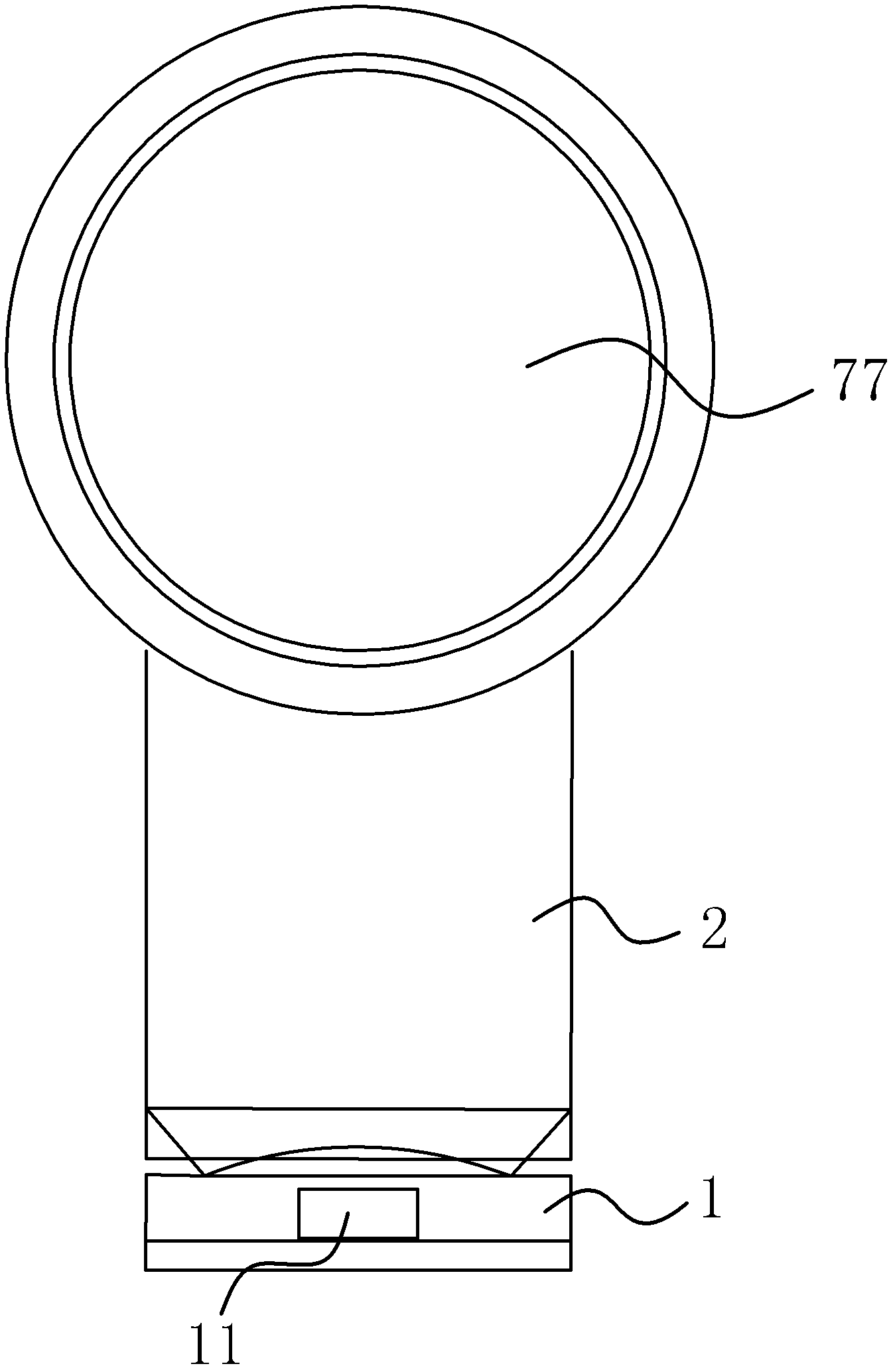
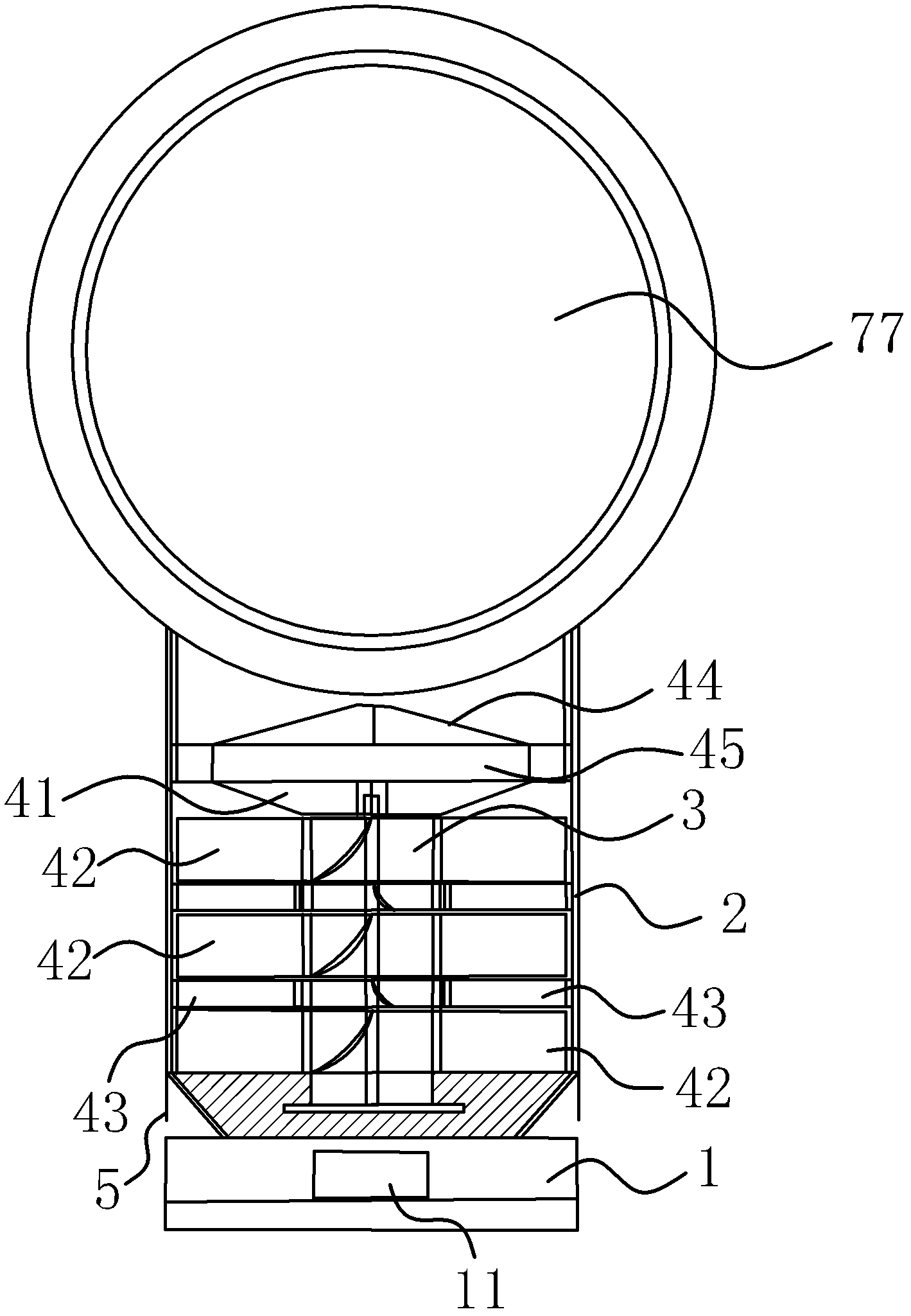
[0051] Such as figure 1 As shown, the bladeless fan of the low-speed supercharger impeller includes an upper part, a middle part and a lower part mechanically connected, wherein the upper part is an air outlet assembly, and the middle part includes a cylindrical fan housing 2, a supercharger impeller assembly, and an air intake assembly. And motor 3, the bottom is base 1. Wherein, the casing 2 has an air inlet and an air outlet, the air outlet assembly is arranged at the air outlet, and the air inlet assembly is arranged at the air inlet. Such as figure 1 with figure 2 As shown, there is a remote control panel 11 on the base 1. The remote control panel 11 is also called an electronic induction receiver, which is used to receive the signal sent by the remote controller and control the speed of the motor. The speed of the motor is to ensure that the fan outlet The basis of the size of the wind, the greater the speed, the greater the wind blown by the fan. The connecting par...
Embodiment 2
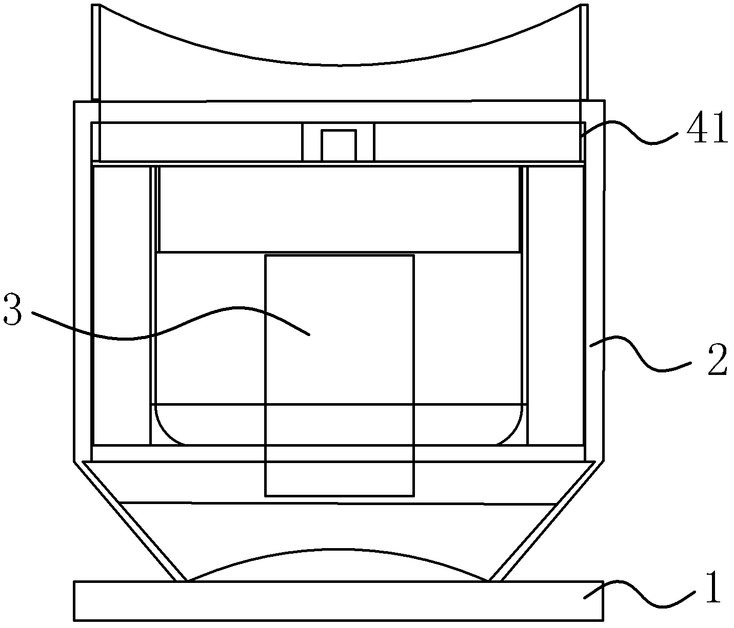
[0061] The structural principle of this embodiment is basically the same as that of Embodiment 1, the difference is that, as image 3 As shown, the booster impeller assembly adopts a single-stage thickened axial-flow impeller. The positional relationship between most of the components in this embodiment is the same as that in the first embodiment of the booster impeller assembly. With a single-stage thickened axial-flow impeller, the longer the acceleration distance of the air passing through the impeller, the greater the energy obtained. For example, the thickness of the impeller in the past was 20mm. In this embodiment, the thickness of the impeller is increased to 40mm, and the energy of the air increases. The volume is larger than in the past, otherwise the same air volume and air pressure, the speed of the thickened impeller is much smaller. At this time, the rotating speed of the motor 3 can be reduced, and the noise will also be reduced as the rotating speed decreases....
Embodiment 3
[0063] The structural principle of this embodiment is basically the same as that of Embodiment 1, the difference is that, as Figure 4 As shown, the booster impeller assembly is a multi-stage axial flow impeller, and the relationship between other components is basically the same as that in the second embodiment. The multi-stage axial-flow impeller can realize large wind output at low speed, thus reducing noise. The multi-stage axial-flow impeller is the same as the single-stage thickened axial-flow impeller. The only difference is that the single-stage thickened axial-flow impeller can increase the energy at one time, while the multi-stage axial-flow impeller can increase the energy in multiple times. , the results are designed for lower speeds.
PUM
| Property | Measurement | Unit |
|---|---|---|
| Thickness | aaaaa | aaaaa |
| Thickness | aaaaa | aaaaa |
Abstract
Description
Claims
Application Information
 - R&D
- Intellectual Property
- Life Sciences
- Materials
- Tech Scout
- Unparalleled Data Quality
- Higher Quality Content
- 60% Fewer Hallucinations
Browse by: Latest US Patents, China's latest patents, Technical Efficacy Thesaurus, Application Domain, Technology Topic, Popular Technical Reports.
© 2025 PatSnap. All rights reserved.Legal|Privacy policy|Modern Slavery Act Transparency Statement|Sitemap|About US| Contact US: help@patsnap.com


