Method for retarding emission of greenhouse gas by combusting fuel oil

一种温室气体、燃烧室的技术,应用在燃烧方法、燃烧器、燃烧类型等方向,能够解决很难达到节能、减少温室气体、很难体现出燃烧器节能环保的优越性等问题,达到节省燃油、成本低、节省能源的效果

Inactive Publication Date: 2013-08-14
伍镜清
View PDF6 Cites 0 Cited by
  • Summary
  • Abstract
  • Description
  • Claims
  • Application Information

AI Technical Summary

Problems solved by technology

However, it is difficult to reflect the superiority of the burner in energy saving and environmental protection only by a single use.
It is difficult to achieve good results in energy saving and greenhouse gas reduction

Method used


Image

  • Method for retarding emission of greenhouse gas by combusting fuel oil
  • Method for retarding emission of greenhouse gas by combusting fuel oil
  • Method for retarding emission of greenhouse gas by combusting fuel oil

Examples


Embodiment Construction

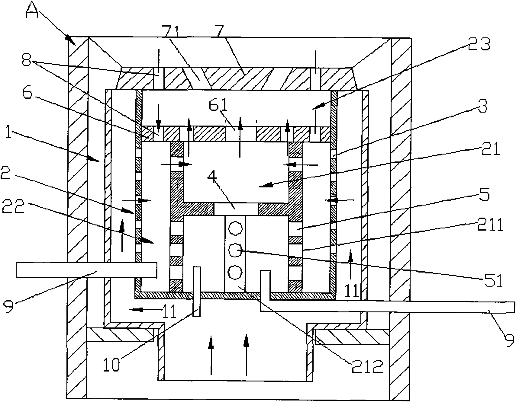
[0017] The method for mitigating greenhouse gas emissions by burning fuel oil of the present invention: the non-heat radiation fuel burner is arranged in the stove A.

[0018] A non-heat radiation fuel burner implementing the above method such as figure 1 As shown, the burner includes a furnace body 1 installed in a furnace A, a furnace body 2 is arranged in the furnace body 1, and a ventilation channel 11 is arranged between the furnace body 1 and the furnace body 2 . The furnace is composed of a shell with a plurality of through holes 3 , and the furnace 2 includes a primary fuel supply combustion chamber 21 , a secondary fuel supply combustion chamber 22 and a blocking chamber 23 . There are two oil delivery ports 9 connected in the furnace 2, each of which is connected by a connecting pipe, one connecting pipe is connected to the lower end of the primary oil supply combustion chamber 21, and the other connecting pipe is connected to the lower end of the secondary oil suppl...


PUM


Abstract

Disclosed is an oil combustion method for reducing greenhouse gas emissions in which an athermal radiation type oil burner is arranged on a stove. The athermal radiation type oil burner includes a furnace body (1) in which a hearth (2) is placed. The hearth (2) composed of a casing with multiple through holes (3) includes a primary oil supply combustion chamber (21), a secondary oil supply combustion chamber (22) and an obstruction chamber (23). The primary oil supply combustion chamber (21) is a casing (211) divided into an upper layer and a lower layer. An interconnected hole (4) is arranged between the two layers. Multiple through holes (5) are distributed on the casing (211) and communicated with the secondary oil supply combustion chamber (22), which is formed by the interval among the casing (211) of the primary oil supply combustion chamber (21), an isolation plats (6) with multiple through holes (61) arranged on the casing (211) and the hearth (2). The obstruction chamber (23) is composed of a sealing plate (7) on the furnace body (1) and the isolation plate (6). Flame holes (71) are arranged on the sealing plate (7). Air flow holes (8) are formed on the corresponding positions of the isolation plate (6) and sealing plate (7), respectively. The secondary oil supply combustion chamber (22) and the obstruction chamber (23) are interconnected with the air flow holes (8). Oil in the burner is continuously spilt, gasified, expanded and compressed for multiple times in the furnace body (1), and oil molecules completely release heat energy and do not release heat radiation again. The burner ensures that generated harmful gas is reduced.

Description

technical field [0001] The invention relates to a method for reducing greenhouse gas emissions, in particular to a method for saving energy and reducing waste gas when fuel is used as fuel. technical background [0002] The atmosphere is filled with different kinds of gaseous compounds, compound particles. Among them, there are a variety of greenhouse gases defined by the "United Nations Framework Convention on Climate Change" as the culprits of global warming: nitrogen dioxide, nitrogen oxides, carbon monoxide, carbon dioxide and sulfur dioxide. These greenhouse gases are mainly caused by the development of human economy and daily life behavior. Such as: aircraft, ships, trucks, power plants, factories, food industry... and other industrial development; cooking, electricity, garbage produced... and so on. Daily life needs. Most of the energy used in industrial production and daily life is fossil fuels (coal, oil and natural gas). At present, liquid fuels are generally use...

Claims


Application Information

Patent Timeline
Patent Type & Authority Patents(China)
IPC IPC(8): F23D5/04
CPCF23D5/04F24C5/12
Inventor 伍镜清
Owner 伍镜清
Why Eureka
Try Eureka