Large high temperature resistant flat ceramic jet mill

A jet mill, flat technology, applied in the field of large-scale high-temperature-resistant flat ceramic jet mill, can solve the problems of heavy maintenance workload, material pollution, easy wear, etc., to improve life and reliability, improve product quality, The effect of breaking through the size limit

Active Publication Date: 2011-12-21
JIANGSU PROVINCE YIXING NONMETALLIC CHEM MACHINERY FACTORY
View PDF4 Cites 4 Cited by
  • Summary
  • Abstract
  • Description
  • Claims
  • Application Information

AI Technical Summary

Problems solved by technology

[0003] The existing flat jet mills are mainly small and medium-sized equipment, and the maximum diameter of the inner cavity is about 90cm. This is because it is very difficult to manufacture a large ceramic lining of this size, so the current common manufacturing method is a flat metal lining. Crush and weld 1mm thick cemented carbide on the inner wall of the upper and lower discs. Although the price of this metal lining is moderate, it can basically meet the performance of high temperature resistance, but the effect of use is not ideal. In general, at least once a week is required, not only the maintenance workload is heavy, but also the downtime has a great impact on the entire assembly line, and automatic and continuous production cannot be realized, which greatly restricts the improvement of output and efficiency
The solder impurities peeled off after wear will also pollute the material, resulting in a reduction in product purity and quality
[0004] The applicant has long been committed to the improvement and improvement of large-scale high-temperature-resistant flat jet mills. In the Chinese patent "CN200320120697.3---improved flat jet mills" applied many years ago, he also tried to use block-type alumina The inner lining is fixed on the inner wall of the upper and lower metal covers with high-temperature-resistant cement or countersunk screws. However, in actual use, due to the large difference in expansion coefficient between metal and ceramics, the ceramic lining will be cracked and fall off, so it is difficult to make a breakthrough.

Method used


Image

  • Large high temperature resistant flat ceramic jet mill
  • Large high temperature resistant flat ceramic jet mill
  • Large high temperature resistant flat ceramic jet mill

Examples


Embodiment Construction

[0028] The specific implementation manner of the present invention will be described below in conjunction with the accompanying drawings.

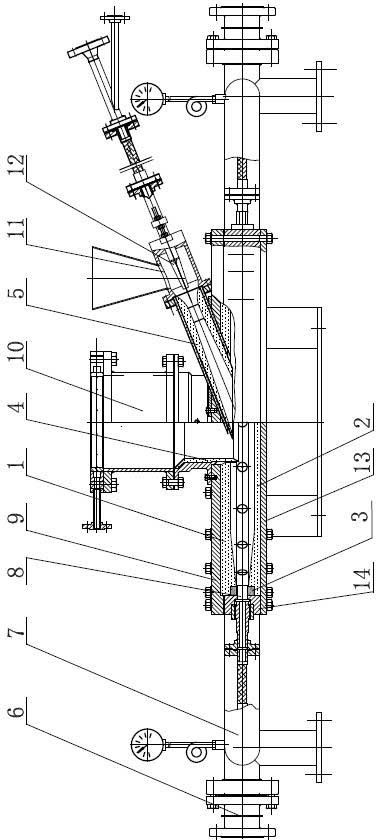
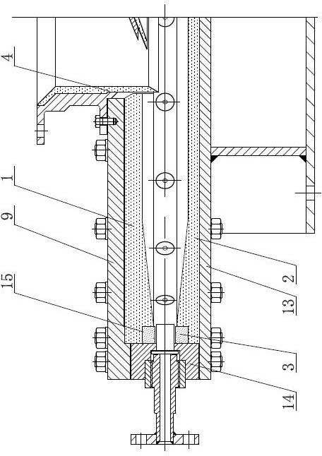
[0029] The high-temperature-resistant flat ceramic airflow pulverizer of the present invention comprises: an upper cover lining 1, a lower cover lining 2, a middle ring lining 3, a discharge port lining 4, a feeding Venturi tube lining 5, a pulverizing Working fluid inlet 6, pulverizing working fluid distribution pipe 7, pulverizing working fluid alloy nozzle 8, metal upper cover 9, discharge port 10, feeding pipe 11, feeding working fluid alloy nozzle 12, metal lower cover 13, metal middle ring 14 , stop 15.

[0030] Such as figure 1 As shown, the basic structure of the present invention is similar to the existing small and medium-sized flat ceramic jet mills. The metal upper cover 9 of the flat disc type, the metal middle ring 14 and the metal lower cover 13 are buckled up and down to form a closed crushing interior. cavity; the center...


PUM


Abstract

The invention discloses a large high-temperature resistance flat type ceramic jet mill. In the jet mill, a metal upper cover, a middle ring and a lower cover are buckled one another to form a flat circular disc, wherein an upper cover liner is arranged inside the upper cover, a lower cover liner is arranged inside the lower cover, and middle ring liners are arranged on outer edges of the upper cover liner and lower cover liner; and the upper cover liner, the lower cover liner and the middle ring liners form a closed crushing cavity. On the flat type jet mill, reaction-bonded silicon carbide is adopted as a liner material, the abrasive resistance is good, and the finished product quality is greatly improved; and according to the block structure of the invention, the manufacture difficulty of the reaction-bonded silicon carbide liner component is greatly reduced, the size limitation to conventional production equipment is broken through, so that a large high-temperature resistance flat type ceramic jet mill with the diameter of over 1m can be manufactured, and the jet mill is in the international leading position to meet the material crushing production requirement of automation, high yield and high quality.

Description

technical field [0001] The invention relates to the field of chemical material equipment, in particular to a large-scale high-temperature-resistant flat ceramic airflow pulverizer lined with reaction sintered silicon carbide. Background technique [0002] Flat jet mills are more and more widely used in industry due to their excellent crushing performance; with the development of science and technology, the demand for ultra-fine powders continues to increase, objectively requiring jet mills Large-scale to increase the output per unit time. Using superheated steam as the crushing medium has excellent crushing effect, and the energy consumption is only a quarter of the cost of the compressed air working medium, so a jet mill with high temperature resistance is required. Moreover, the requirements for the grade of ultra-fine powder products are getting higher and higher, and the pollution of the product by the lining of the pulverizer is required to be as small as possible; A ...

Claims


Application Information

Patent Timeline
Patent Type & Authority Applications(China)
IPC IPC(8): B02C19/06
Inventor 丁红卫冯家迪丁伟群何卫平钱均新
Owner JIANGSU PROVINCE YIXING NONMETALLIC CHEM MACHINERY FACTORY
Why Eureka
Try Eureka