A frequency compensation device for a current mode dc-dc converter

A DC-DC and frequency compensation technology, which is applied in the direction of output power conversion device, conversion of DC power input to DC power output, and adjustment of electrical variables, can solve the problems of slow transient response speed and small bandwidth, and achieve faster transient Effects of state response, large output resistance, and high DC gain

Active Publication Date: 2011-12-21
WUHAN UNIV
View PDF4 Cites 17 Cited by
  • Summary
  • Abstract
  • Description
  • Claims
  • Application Information

AI Technical Summary

Problems solved by technology

[0015] Using dominant pole frequency compensation, although there is only one pole in the unity gain bandwidth, its disadvantage is that the bandwidth is very small, and the large compensation capacitor makes the transient respons

Method used


Image

  • A frequency compensation device for a current mode dc-dc converter
  • A frequency compensation device for a current mode dc-dc converter
  • A frequency compensation device for a current mode dc-dc converter

Examples


Embodiment

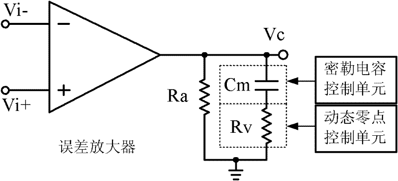
[0058] image 3 The circuit of the frequency compensation network improved by the present invention includes an error amplifier and a frequency compensation circuit.

[0059] Figure 4 The circuit diagram of the error amplifier is given, which adopts a folded cascode structure and consists of a differential input circuit, a common gate amplifier circuit and a current mirror load. The error amplifier includes: a differential input circuit: including a first differential input PMOS transistor M1, a second differential input PMOS transistor M2, and a current mirror PMOS transistor M11; a common-gate amplifier circuit: including a first common-gate NMOS amplifier tube M3, a second common-gate Grid NMOS amplifier tube M4, third common grid NMOS amplifier tube M5 and fourth common grid NMOS amplifier tube M6; a cascode current mirror load: including the first current mirror PMOS load tube M7, the second current mirror PMOS load tube M8 , the third current mirror PMOS load transist...


PUM


Abstract

The invention relates to a frequency compensating device, in particular to a current model frequency compensating device of a DC-DC (direct current-direct current) converter. The device is characterized by comprising an error amplifier and a frequency compensating circuit connected in sequence. The device disclosed by the invention has the following advantages that: 1, the instant response of a frequency compensating system is accelerated, a compensating capacitor can be directly integrated in a chip, thus, the area of the overall circuit is saved; 2, a dynamic zero point changed with the change of the loaded current can be generated to counteract the pole omega 1; and 3, the error amplifier adopts a foldable common source common grid structure, thus, a high DC gain and a large output resistance can be provided, and a low frequency domain pole can be produced only at the output end of an operational amplifier.

Description

technical field [0001] The invention relates to a frequency compensation device, in particular to a frequency compensation device of a current mode DC-DC converter. [0002] Background technique [0003] With the rapid development of power electronic technology, the relationship between power electronic equipment and people's work and life is increasingly close, and electronic equipment is inseparable from a reliable power supply. In the 1990s, the computer power supply fully realized the switching power supply, and took the lead in completing the computer. In the early 21st century, switching power supply (switch-mode power converter, SMPC) entered the fields of various electronic and electrical equipment. Switching power supply has been widely used in program-controlled switches, communications, electronic testing equipment power supply, control equipment power supply, etc. , but also promoted the rapid development of switching power supply technology. [0004] At presen...

Claims


Application Information

Patent Timeline
IPC IPC(8): H02M3/158
Inventor 江金光汪家轲
Owner WUHAN UNIV
Why Eureka
Try Eureka