
A random time-to-digital converter

一种数字转换器、随机时间的技术,应用在时间数字转换器、应用随机技术转换、模/数转换等方向,能够解决功耗、面积和硬件消耗增大等问题,达到消除器件失配和工艺、面积减半的效果

Inactive Publication Date: 2011-12-21
SOUTHEAST UNIV WUXI CAMPUS
View PDF7 Cites 11 Cited by
  • Summary
  • Abstract
  • Description
  • Claims
  • Application Information

AI Technical Summary

Problems solved by technology

However, since the achievable resolution is directly related to the number of comparators used, the improvement of resolution requires more comparators, and the power consumption, area and hardware consumption will inevitably increase.

Method used


Image

  • A random time-to-digital converter
  • A random time-to-digital converter
  • A random time-to-digital converter

Examples


Embodiment Construction

[0022] Below in conjunction with accompanying drawing, technical scheme of the present invention is described in further detail:

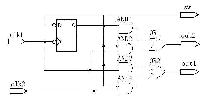
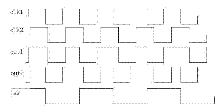
[0023] Such as figure 1 As shown, the random time-to-digital converter includes three parts: input switching circuit, STDC array and encoder. The input switching circuit is realized by digital logic circuit. The STDC array is composed of 64 identical comparator units. The encoder is composed of sw Signal controlled 64-7 encoder. The two clock input signals clk1 and clk2 are connected to the input terminals of the input switching circuit, the outputs out1 and out2 of the input switching circuit are respectively connected to the input terminals of each comparator in the STDC array, and the output signal sw is connected to the encoder as a control signal, which is determined by A frequency-divided-by-two signal triggered by the falling edge of clk1. The 64-bit judgment result generated by STDC is connected to the encoder, and the encoder generates 7...


PUM


Abstract

The invention discloses a stochastic time-digital converter, which comprises an input switching circuit, a stochastic time-digital converter (STDC) array and an encoder. A clock circuit inputs two clock signals into the two input ends of the input switching circuit respectively. The input switching circuit transmits the two clock signals input by the clock signal to the two input ends of the STDC array in form of alternate transposition, and simultaneously outputs a triggering control signal to the encoder. Each comparator in the STDC array independently judges the speed of each clock signal, and transmits a judgment result to the encoder for summarization. The encoder outputs the magnitude and plug-minus of a phase difference between the two clock signals. The number of equivalent comparators in the STDC array is multiplied by utilizing the stochastic characteristics of the STDC to maximally eliminate device mismatching and the influence of a process, power voltage and temperature on the circuit; and compared with the conventional STDC circuit, the STDC has the characteristics of hardware saving, low power consumption and small area.

Description

technical field [0001] The invention relates to a random time-to-digital converter with an input switching circuit, which can identify the time difference between the rising edges of two clock signals and express it in digital form. Background technique [0002] TDC (Time-Digital Converter, Time-Digital Converter) is widely used in integrated circuits, and is mainly used to provide phase discrimination for digital phase-locked loops. In addition, many applications such as nuclear medicine imaging, laser range detection, and particle half-life detection in high-energy physics rely on TDC to identify small time (phase) differences. The TDC is implemented with an all-digital process, and has the advantage of good portability as the process size gradually shrinks. In addition, the all-digital TDC circuit has better noise immunity characteristics and lower power consumption. Because TDC quantizes the time (phase) difference into digital output, compared with the traditional fr...

Claims


Application Information

Patent Timeline
Patent Type & Authority Applications(China)
IPC IPC(8): H03M1/04H03M1/50
CPCG04F10/005H03M1/50H03M1/04
Inventor 吴建辉王子轩张萌黄成陈超黄福青吉新村江平
Owner SOUTHEAST UNIV WUXI CAMPUS
Learn More