Flat spiral heat exchange tube and its on-line tube processing technology

A technology of spiral heat exchange tube and processing technology, applied in the field of metal tube processing, can solve the problem that the heat exchange area and the heat exchange efficiency are difficult to be greatly improved, the cold working process is difficult to ensure the quality of the finished product, and the finished product specification and length of the heat exchange tube are limited. problem, to achieve the effect of improving heat exchange efficiency, low cost and convenient manufacturing

Inactive Publication Date: 2011-12-28
SHANGHAI KEMI STEEL TUBE
View PDF0 Cites 2 Cited by
  • Summary
  • Abstract
  • Description
  • Claims
  • Application Information

AI Technical Summary

Problems solved by technology

[0011] 1. Due to the specifications of cold processing equipment, the finished heat exchange tubes are greatly limited in terms of specifications and length;
[0012] 2. Due to the cold processing steps, the loss of raw materials is relatively large;
[0013] 3. Due to the complex cold processing process, the processing accuracy of the product is uneven;
[0014] 4. It is difficult to guarantee the quality of the finished product by the inspection method and inspection method of the cold processing process;
[0015] 5. Limited by the processing technology, the tube making efficiency is not high;
[0016] 6. Most of these four types of heat exchange tubes have special shapes, which bring a lot of inconvenience to the production of heat exchanger equipment such as the disposal of bellows and baffles of outer grooved tubes;
[0017] 7. These four types of heat exchange tubes have been cold-worked, and there are residual stresses on the tube body, which will form turbulent flow when the medium passes through, which strengthens the local corrosion of the heat exchange tubes, so it has a certain impact on the service life of the heat exchanger equipment. negative impact
[0018] Due to the above reasons, the heat exchange tubes in the prior art have entered a technical bottleneck, and it is difficult to greatly increase the heat exchange area and heat exchange efficiency, which restricts the development of heat exchangers and is difficult to meet the needs of the market

Method used


Image

  • Flat spiral heat exchange tube and its on-line tube processing technology
  • Flat spiral heat exchange tube and its on-line tube processing technology
  • Flat spiral heat exchange tube and its on-line tube processing technology

Examples


Embodiment 1

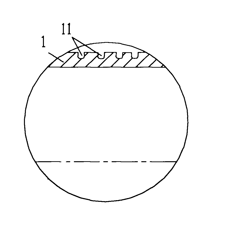
[0055] Such as Figure 5 As shown, the flat spiral heat exchange tube 1 of the present invention is a metal welded pipe with a certain length, such as austenitic stainless steel welded pipe, carbon steel welded pipe, titanium and titanium alloy welded pipe, nickel and nickel alloy welded pipe, or austenitic - Ferritic duplex steel welded pipes, etc.

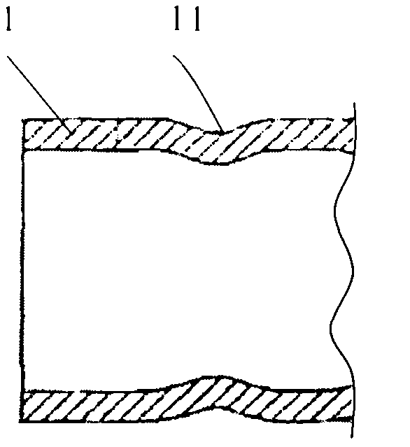
[0056] Figure 5 Its cross-sectional shape is shown, Image 6 Shown is the helical shape of its outer surface. The inner surface of the pipe body 2 is a smooth surface formed by connecting two parallel surfaces and two arc transition surfaces.

[0057] The inside of the pipe body 2 forms a medium channel 3 through which the heat exchange medium flows.

[0058] The tube body 2 has a flat cross section, and divides the medium channel 3 into two side heat exchange areas 31 and a middle heat exchange area 32 . The cross-sectional areas of the two side heat exchange areas 31 are approximately the same as the cross-sectional areas...

Embodiment 2

[0067] The structure of the flat spiral heat exchange tube of this embodiment is basically the same as that of the above embodiments, both including a tube body, the difference is that in this embodiment, there are straight tube sections at both ends of the tube body. The straight pipe section and the flat spiral section should transition smoothly without sharp deformation.

[0068] The flat spiral heat exchange tube with the straight pipe section has better assembly and sealing performance in the assembly and processing of heat exchange equipment.

Embodiment 3

[0070] The online tube-making process of the flat spiral heat exchange tube 1 of the present invention at least includes:

[0071] Step 1, obtaining the tube body 2 .

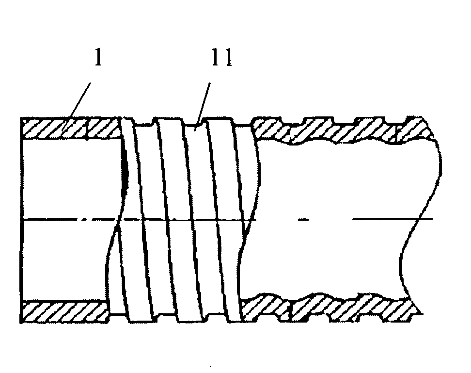
[0072] In this embodiment, the pipe body 2 is a metal welded pipe, and its cross section is formed by connecting two parallel surfaces and two arc transition surfaces. combine Figure 7 As shown, the pipe body 2 is obtained through a pressing process.

[0073] The pressing equipment mainly includes a series of brackets 401, 402, 403, each bracket is respectively provided with upper rollers 411, 412, 413 and lower rollers 421, 422, 423, and a series of left rollers are respectively arranged on both sides of the pipe body 2. Roller, right roller (not shown in the figure). A series of gradually deformed flat stampers are arranged or formed on each roller, and these flat stampers all have rotating lines.

[0074] The flat spiral tube body 2 is obtained by stepwise deformation through four-side extrusion.

[00...


PUM


Abstract

The invention discloses a flat spiral heat exchange tube, which at least includes a tube body, the tube body surrounds and forms a medium passage; the tube body has a flat cross section, and the tube body has a spiral outer surface. The present invention also provides an online tube-making process for the above-mentioned flat spiral heat exchange tube. The invention has low cost and convenient manufacture, and is suitable for use as a tube for high-efficiency heat exchangers or heat exchange equipment in various industries such as petroleum, chemical industry, chemical fertilizer, boiler, pharmaceutical, food, electric power, nuclear energy, environmental protection, and heat supply.

Description

technical field [0001] The invention relates to the technical field of metal tube processing, in particular to a flat spiral heat exchange tube used for heat exchange equipment such as heat exchangers. The present invention also relates to the processing technology of the aforementioned flat spiral heat exchange tube. Background technique [0002] According to the standard of GB / T24590-2009 "Special Tubes for High Efficiency Heat Exchangers", the current high-efficiency special tubes for heat exchangers in my country are divided into four types, namely T-groove tubes, corrugated tubes, inner wave and outer threaded tubes, Inner groove tube. The biggest thing they have in common is that they are all heat exchange tubes manufactured and processed on metal base tubes (straight tubes) by cold working process. [0003] Such as figure 1 As shown, in the T-shaped groove pipe in the prior art, dense spiral T-shaped grooves 11 are formed on the outer wall of the metal base pipe 1 b...

Claims


Application Information

Patent Timeline
Patent Type & Authority Applications(China)
IPC IPC(8): F28F1/34B21C37/08B21C37/15
CPCY02P20/10
Inventor 孔祥锋
Owner SHANGHAI KEMI STEEL TUBE
Why Eureka
Try Eureka