Ultra-medium UHF band-pass filter

A technology of ultra-high frequency band and supernormal medium, which is applied in the direction of waveguide devices, electrical components, circuits, etc., can solve the problems of large size, large loss, and difficult filter, etc., and achieve low insertion loss, low production cost, and easy Processing effect

Inactive Publication Date: 2011-12-28
HARBIN INST OF TECH
View PDF3 Cites 8 Cited by
  • Summary
  • Abstract
  • Description
  • Claims
  • Application Information

AI Technical Summary

Problems solved by technology

[0004] In order to solve the problem of large size and large loss in the current resonant wavelength filter, the research work has been fully carried out. It is an inevitable trend to replace the traditional filter with the filter of the supernormal dielectric structure. The supernormal dielectric structure widely used in the filter mainly has openings Resonant ring (SRR) and complementary split resonant ring (CSRR), the higher the operating frequency band, the more difficult it is to produce a filter with high performance (such as large bandwidth and low insertion loss). At present, the working frequency band of supernormal media filters is mainly Below 10GHz

Method used


Image

  • Ultra-medium UHF band-pass filter
  • Ultra-medium UHF band-pass filter
  • Ultra-medium UHF band-pass filter

Examples


specific Embodiment approach 1

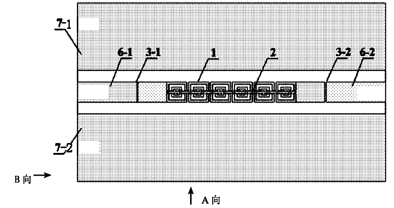
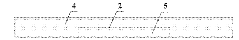
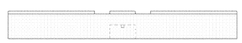
[0009] Specific implementation mode one: combine figure 1 Describe this embodiment. This embodiment includes multiple split resonant rings 1, metal strips 2, No. 1 capacitor 3-1, No. 2 capacitor 3-2, substrate 4, air slot 5, No. 1 signal line 6-1, No. 2 capacitor No. signal wire 6-2, No. 1 ground wire 7-1 and No. 2 ground wire 7-2 have a rectangular parallelepiped air slot 5 upward at the midline position of the lower surface of the base 4, and the metal strip 2 is bonded to the top of the air slot. In the middle, the split resonant ring 1 is composed of an inner ring and an outer ring of the same material. The opening directions of the inner ring and the outer ring are opposite and in the same plane. A plurality of split resonant rings 1 are arranged side by side in a row, non-contact placed on the metal On the upper surface of the substrate 4 directly above the bar 2, the outer ring openings of all the multiple split resonant rings 1 are turned to the right, and the inner ri...

specific Embodiment approach 2

[0011] Specific implementation mode two: combination figure 1 This embodiment is described. The difference between this embodiment and Embodiment 1 is that the total area of ​​the ultra-high frequency bandpass filter of the meta-media is 15.5mm×9mm. Other components and connections are the same as those in Embodiment 1.

specific Embodiment approach 3

[0012] Specific implementation mode three: combination image 3 This embodiment is described. The difference between this embodiment and Embodiment 1 is that the substrate 4 is made of silicon with a relative permittivity of 11.9, and a thickness of 1 mm. Other components and connections are the same as those in Embodiment 1.


PUM


Abstract

The invention discloses a supernormal medium ultrahigh frequency band pass filter, and relates to a wireless communication microwave filter, and the filter can be used for solving the problem that the working frequency range of the existing supernormal medium filter is mainly below 10GHz. The filter comprises a plurality of split ring resonators, a metal bar, a No.1 capacitor, a No.2 capacitor, a base, an air groove, a No.1 signal line, a No.2 signal line and an earth wire; the neutral line part of the lower surface of the base is provided with the rectangular air groove upward; the metal bar is bonded at the middle of the top of the air groove; the split ring resonators consist of inner rings and outer rings which are made of a same material; the plurality of split ring resonators are ranked into a line and are placed on the upper surface of the base right above the metal bar in a non-contact mode; the right end of the No.1 signal line is communicated with the outer rings of the ring resonators at the left end of a split ring resonator array; the left end of the No.2 signal line is communicated with the outer rings of the split ring resonators at the right end of the ring resonator array; the left end of the No.1 signal line is an input end, and the right end of the No.2 signal line is an output end, and the No.1 signal line and the No.2 signal line are used for filtering harmonic waves and restraining stray in a wireless communication system.

Description

technical field [0001] The invention relates to a microwave filter for wireless communication. Background technique [0002] Filters are very important in wireless communication systems. They play a role in frequency band and channel selection, and can filter out harmonics and suppress spurs. A bandpass filter allows signals of a given frequency band or channel to pass while rejecting signals with frequencies below and above the passband. With the rapid development of wireless communication and the high integration of microwave circuits, the filter as a key component of the communication system is also required to develop in the direction of high performance and miniaturization. Planar structure filters have the advantages of small size, easy processing by photolithography technology, and easy compatibility with other active circuit components, etc., and are placed in high expectations in the design of modern filters. New technologies for miniaturization and performance im...

Claims


Application Information

Patent Timeline
Patent Type & Authority Applications(China)
IPC IPC(8): H01P1/20H01P1/212
Inventor 傅佳辉陈鹏吴群孟繁义潘威李浩宇
Owner HARBIN INST OF TECH
Why Eureka
Try Eureka