Welding method of coaxial diode and circuit board

A welding method and circuit board technology, applied in the direction of circuits, electrical components assembling printed circuits, electrical components, etc., can solve the problems of welding failure, thermal stress hidden dangers, etc., to ensure reliability, ensure the strength of solder joints, and improve the uniform extension. effect of length

Active Publication Date: 2011-12-28
THE 13TH RES INST OF CHINA ELECTRONICS TECH GRP CORP
View PDF3 Cites 2 Cited by
  • Summary
  • Abstract
  • Description
  • Claims
  • Application Information

AI Technical Summary

Problems solved by technology

If there is no effective stress relief channel, it will ...

Method used


Image

  • Welding method of coaxial diode and circuit board
  • Welding method of coaxial diode and circuit board
  • Welding method of coaxial diode and circuit board

Examples


Embodiment Construction

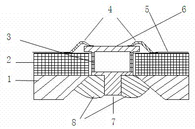
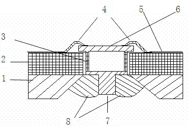
[0023] A welding method for a coaxial diode and a circuit board, characterized in that the method comprises the following steps:

[0024] A. Circuit board welding: Enamel Sn96.5Ag3.5 solder on the copper carrier 1 and the circuit board welding surface composed of microstrip line 5 and dielectric material 2, and solder the circuit board and copper carrier 1 on a heating table at 235°C Together, press with a briquetting block and remove after cooling;

[0025] B. Drilling and chamfering: On the circuit board and the copper carrier 1, according to the position of the assembly drawing, drill an assembly through hole, the diameter of the through hole is ф1.3mm; use a 120 ° Φ5 drill bit on the copper carrier 1 chamfering, the depth of the chamfering is the thickness of the copper carrier 1, forming a tapered hole, and enamel In52Sn48 solder at the chamfering position;

[0026] C. Carrier and diode pre-tinning: tinning In52Sn48 soldering tin on the welding part of the tapered hole a...


PUM


Abstract

The invention discloses a welding method of a coaxial diode and a circuit board. A gold-plating copper strip is used as a stress release bridge at the anode of the diode to replace the original solder hard link, so as to solve the problem of stress caused by the longitudinal coefficient of thermal expansion of the circuit board; an In52Sn48 solder is adopted, thus the heat-resistance fatigue capability and uniform elongation are improved, and the reliability of a welding spot is ensured; and the welding area of the cathode of the diode is increased, and the welding spot intensity is ensured by arranging a collet. By utilizing the welding method provided by the invention, the thermal stress caused by different coefficients of thermal expansion of a circuit board material and a diode ceramic body material, and the welding failure or potential hidden danger caused by the thermal stress are resolved, thus improving the quality of the welding spot and the reliability of the product.

Description

technical field [0001] The invention relates to a method for manufacturing a microwave device, in particular to a method for welding a coaxial diode and a circuit board. Background technique [0002] The aerospace industry standard of the People's Republic of China QJ3172-2003 "Technical Requirements for Microwave Component Installation" stipulates that the assembly of cylindrical microwave diodes should use a concave soldering iron tip to weld the ground end of the diode. Cover them all. When soldering electrodes on the surface of the circuit board, the protruding part of the solder joints should not be greater than 2mm, and the solder should not flow to the top of the electrodes. It only requires the shape of the solder joints, and mainly has the following problems and defects: [0003] A. There is no effective description of the thermal stress caused by the different thermal expansion coefficients of the dielectric material and the diode material. [0004] B. No stres...

Claims


Application Information

Patent Timeline
IPC IPC(8): H05K3/34H01L21/60
CPCH01L2224/48091H01L2924/00014
Inventor 韩建栋史金霞王志强王玉田
Owner THE 13TH RES INST OF CHINA ELECTRONICS TECH GRP CORP
Why Eureka
Try Eureka