
Powder conveying device

A conveying device and powder technology, which can be used in conveying bulk materials, conveyors, transportation and packaging, etc., and can solve problems such as high failure rate, poor liquid slag discharge, and safety accidents.

Active Publication Date: 2012-01-04
陕西省煤化工工程技术研究中心 +1
View PDF8 Cites 6 Cited by
  • Summary
  • Abstract
  • Description
  • Claims
  • Application Information

AI Technical Summary

Problems solved by technology

This kind of transportation method often has a huge system and complicated process, and this technology usually adopts the method of adding a certain amount of high-pressure gas in the transportation pipeline to maintain the transmission power in the pipeline, resulting in an increase in the consumption of carrier gas, high operating requirements, and continuous operation. , poor stability
Taking the dry powder pressurized coal gasification process in energy and chemical industry as an example, the existing gasification process powder transportation technology consists of multiple units such as normal pressure, pressurization, variable pressure, feeder and weighing meter, and is equipped with a large number of pressure , temperature and material level indicating instruments, in order to ensure the continuity of conveying, the pneumatic pressurization system is generally equipped with a booster hopper and two alternately used pressurization hoppers for joint use, the process is cumbersome, there are many constraints, and the failure rate is high. big investment
The non-advanced dry pulverized coal conveying system seriously affects the control of the gasifier temperature, which in turn leads to large fluctuations in the furnace temperature, unstable content of active ingredients, poor liquid slag discharge, high trigger shutdown rate, and what is even more likely to cause accidents, casualties

Method used


Image

  • Powder conveying device
  • Powder conveying device
  • Powder conveying device

Examples


Embodiment 1

[0071] Example 1 : Use the powder conveying device of the present invention to transport Yunnan Xiaolongtan lignite

[0072] The moisture content of Yunnan Xiaolongtan lignite was determined according to the method of GB / T483-1998 "General Methods for Coal Analysis Test".

[0073] The particle size distribution of Yunnan Xiaolongtan lignite was determined according to the standard sample sieving method.

[0074] The measurement results of moisture content and particle size distribution of Yunnan Xiaolongtan lignite are listed in Table 1.

[0075] Table 1: Moisture content and particle size distribution of Yunnan Xiaolongtan lignite

[0076]

[0077] The implementation is as follows:

[0078] Setting conditions: the flow rate of pulverized coal is 1t / h, and the pressure of pulverized coal discharged from the powder conveying device of the present invention is 5.0MPa.

[0079] The implementation process and its conditions are as follows: about 2t of pulverized coal that ...

Embodiment 2

[0080] Example 2 : use the powder conveying device of the present invention to transport the bituminous coal in Shenfu, Shaanxi

[0081]The moisture content of Shaanxi Shenfu bituminous coal was determined according to GB / T483-1998 "Regulations on General Methods of Coal Analysis Test".

[0082] The particle size distribution of Shaanxi Shenfu bituminous coal was determined according to the standard sample sieving method.

[0083] The measurement results of water content and particle size distribution of Shaanxi Shenfu bituminous coal are listed in Table 1.

[0084] Table 1: Moisture content and particle size distribution of Shaanxi Shenfu bituminous coal

[0085]

[0086] The implementation is as follows:

[0087] Setting conditions: the flow rate of pulverized coal is 20t / h, and the pressure of pulverized coal out of the system is set to 7.0MPa.

[0088] The implementation process and its conditions are as follows:

[0089] Using the system calibrated in Example 1, ...


PUM


Abstract

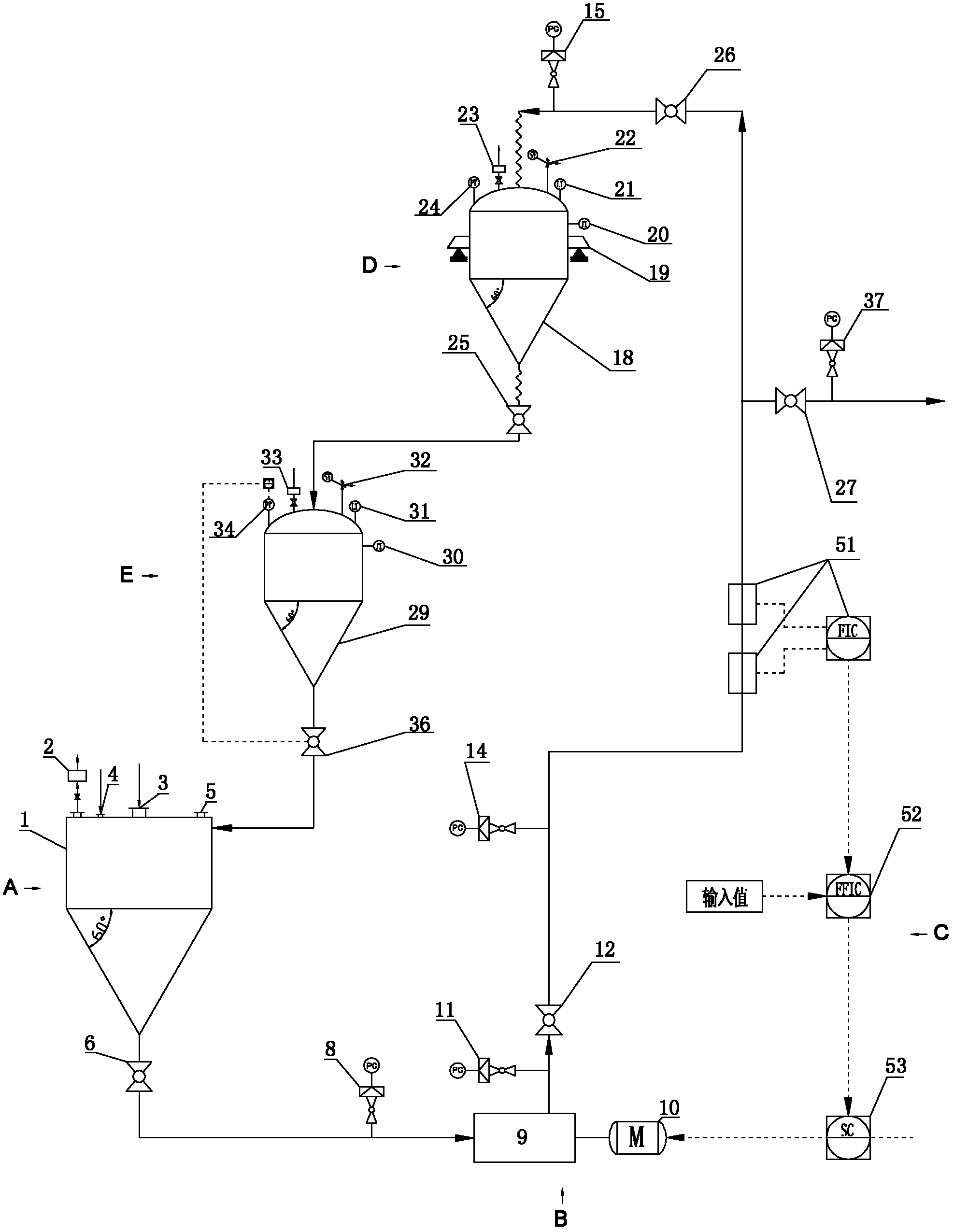
The invention relates to a powder conveying device. The device is composed of a powder storage system A, a powder pressing and conveying system B, a powder flow monitoring and adjusting system C, a powder weighing system D and a powder recycling system E; the power firstly enters the powder storage system A, and then enters the powder pressing and conveying system B under the effect of gravity and negative pressure of a pressurizer; after the powder flow monitoring and adjusting system C performs flow control, the powder is discharged in a continuous manner; when a constant-flow state is established or a verification coefficient of a measurement instrument is obtained before driving, the pressurized powder discharged from the powder flow monitoring and adjusting system C enters the powderweighing system D through valve switch, and the powder weighing system D weighs and computes the verification coefficient of the powder flow measurement instrument; and then the powder is depressurized by the powder recycling system E and returns to the powder storage system to be recycled. The device has a simple structure and a large flow adjusting range, requires small investment, is continuous and stable in operation, saves energy and is environmentally-friendly. Therefore, the powder conveying device provided by the invention has strong adaptability and a remarkably wide application prospect.

Description

【Technical field】 [0001] The invention belongs to the technical field of powder conveying. More specifically, the present invention relates to a powder conveying device. 【Background technique】 [0002] The high-concentration dense phase conveying technology is a solid particle (powder) conveying technology proposed relative to the low-concentration dilute phase conveying technology. As we all know, the high-concentration dense-phase conveying technology of powder generally has the characteristics of low energy consumption, large conveying capacity, wide conveying range, small abrasion of pipelines and materials, saving carrier gas consumption and gas power source, and saving pipeline material consumption. At the same time, the high-concentration dense-phase conveying technology is also conducive to reducing the generation of static electricity in pipeline transportation and improving the safety of conveying flammable and explosive materials. For occasions with heat demand,...

Claims


Application Information

Patent Timeline
IPC IPC(8): B65G53/16B65G53/58
Inventor 门长贵张勇徐宏伟贺根良罗进成朱春鹏韦孙昌
Owner 陕西省煤化工工程技术研究中心
Learn More