Exhaust gas waste heat recovery and emission reduction comprehensive application system for coal-fired boiler in thermal power plant

A technology for thermal power plants and coal-fired boilers, applied in indirect carbon dioxide emission reduction, preheating, combustion methods, etc., to achieve the effects of improving heat consumption, reducing the number of power sources, and high dust removal efficiency

Active Publication Date: 2012-01-04
SOUTHWEST ELECTRIC POWER DESIGN INST OF CHINA POWER ENG CONSULTING GROUP CORP
View PDF6 Cites 31 Cited by
  • Summary
  • Abstract
  • Description
  • Claims
  • Application Information

AI Technical Summary

Problems solved by technology

[0003] A typical low-temperature economizer system uses flue gas to heat condensate water to improve the efficiency of

Method used


Image

  • Exhaust gas waste heat recovery and emission reduction comprehensive application system for coal-fired boiler in thermal power plant
  • Exhaust gas waste heat recovery and emission reduction comprehensive application system for coal-fired boiler in thermal power plant
  • Exhaust gas waste heat recovery and emission reduction comprehensive application system for coal-fired boiler in thermal power plant

Examples


Embodiment 1

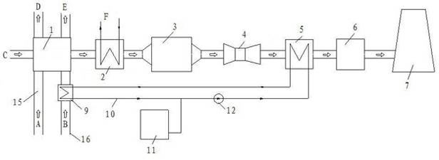
[0041] Such as figure 2 As shown, a coal-fired boiler exhaust heat recovery and emission reduction comprehensive application system in a thermal power plant, along the flow direction of the flue gas, an air preheater 1, a first Low temperature economizer 2, low and low temperature dust collector 3, induced draft fan 4, second low temperature economizer 5, desulfurization island 6, the inlet of the air preheater 1 is respectively connected with the cold primary air pipeline 15 and the cold secondary air pipeline 16 The cold secondary air pipeline 16 is provided with a secondary air heater 9, and the secondary air heater 9 communicates with the second low-temperature economizer 5 through the water medium pipeline 10, and the water medium The pipeline 10 is provided with an expansion tank 11 and a water pump 12 . There is no heating device on the cold primary air duct 15 .

[0042] The working process of this embodiment: the flue gas C comes out of the air preheater, passes th...

Embodiment 2

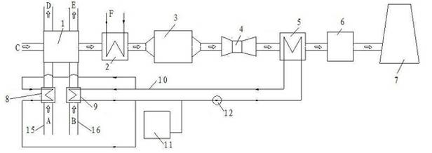
[0044] Such as image 3 As shown, a coal-fired boiler exhaust heat recovery and emission reduction comprehensive application system in a thermal power plant, along the flow direction of the flue gas, an air preheater 1, a first Low temperature economizer 2, low and low temperature dust collector 3, induced draft fan 4, second low temperature economizer 5, desulfurization island 6, the inlet of the air preheater 1 is respectively connected with the cold primary air pipeline 15 and the cold secondary air pipeline 16 The cold secondary air pipeline 16 is provided with a secondary air heater 9, and the secondary air heater 9 communicates with the second low-temperature economizer 5 through the water medium pipeline 10, and the water medium The pipeline 10 is provided with an expansion tank 11 and a water pump 12 . The cold primary air pipeline 15 is provided with a primary air heater 8 , and the primary air heater 8 and the secondary air heater 9 share the same water medium pipel...

Embodiment 3

[0048] Such as Figure 4 As shown, a coal-fired boiler exhaust heat recovery and emission reduction comprehensive application system in a thermal power plant, along the flow direction of the flue gas, an air preheater 1, a first Low temperature economizer 2, low and low temperature dust collector 3, induced draft fan 4, second low temperature economizer 5, desulfurization island 6, the inlet of the air preheater 1 is respectively connected with the cold primary air pipeline 15 and the cold secondary air pipeline 16 The cold secondary air pipeline 16 is provided with a secondary air heater 9, and the secondary air heater 9 communicates with the second low-temperature economizer 5 through the water medium pipeline 10, and the water medium The pipeline 10 is provided with an expansion tank 11 and a water pump 12 .

[0049] The primary air heater 8 is arranged on the cold primary air pipeline 15, and the primary air heater 8 is connected with the low-pressure heater from the heat...


PUM


Abstract

The invention discloses an exhaust gas waste heat recovery and emission reduction comprehensive application system for a coal-fired boiler in a thermal power plant. In the invention, along the flow direction of flue gas, an air preheater, a first low temperature economizer, a low temperature dust collector, a draught fan, a second low temperature economizer and a desulfuration island are sequentially arranged on a pipe between the boiler and a chimney, wherein, the inlet of the air preheater is respectively communicated with a cold primary air pipe and a cold secondary air pipe; the cold secondary air pipe is provided with a secondary air heater; the secondary air heater is communicated with the second low temperature economizer via a coal-water pipe; the coal-water pipe is provided with an expansion tank and a water pump; and the low temperature economizer is divided into two segments, wherein, one segment is used for heating condensed water, and the other section is used for heating the cold secondary air at the inlet of the air preheater by virtue of a water medium. The exhaust gas waste heat recovery and emission reduction comprehensive application system has the beneficial effects of maximally utilizing the gas waste heat, reducing heat consumption of a machine set, lowering energy consumption of equipment such as the dust collector, the draught fan, a blower and the like, reducing the power consumption rate of the thermal power plant, improving the economical efficiency of the thermal power plant, more efficiently saving the energy consumption, and benefiting construction of the lowcarbon society.

Description

technical field [0001] The invention relates to a comprehensive application system for waste heat recovery and emission reduction of coal-fired boilers in thermal power plants. Background technique [0002] Smoke loss is the most important heat loss in boiler operation, accounting for about 60%-70% of boiler heat loss. The design value of the exhaust gas temperature of boilers burning anthracite, lean coal, and bituminous coal is usually 120°C-130°C, and the design value of exhaust gas temperature of boilers burning lignite is usually around 155°C, and the actual operating exhaust temperature of boilers in thermal power plants in my country is mostly higher than the design value. In order to reduce the loss of exhaust gas, reduce the temperature of exhaust gas and improve the economy of power plants, some projects currently use low-temperature economizers to utilize the waste heat of flue gas. figure 1 It is a schematic diagram of the connection of the existing traditional ...

Claims


Application Information

Patent Timeline
IPC IPC(8): F23J15/06F22D1/36F23L15/00
CPCY02E20/34
Inventor 付焕兴张华伦马爱萍陈卫国唐茂平贺清辉李小群王旭东李陆伟江剑朱瑾
Owner SOUTHWEST ELECTRIC POWER DESIGN INST OF CHINA POWER ENG CONSULTING GROUP CORP
Why Eureka
Try Eureka