Microbial fuel cell and application thereof to degradation of azo dye pollutant

A technology of fuel cells and microorganisms, which is applied in the fields of biochemical fuel cells, fuel cells, battery electrodes, etc., and can solve the problems of high energy consumption and difficult realization.

Active Publication Date: 2012-01-11
GUANGDONG INST OF MICROBIOLOGY GUANGDONG DETECTION CENT OF MICROBIOLOGY
View PDF5 Cites 14 Cited by
  • Summary
  • Abstract
  • Description
  • Claims
  • Application Information

AI Technical Summary

Problems solved by technology

However, the above-mentioned pollutant treatment research using electrodes as electron donors requires an external power source to balance the electrodes in the working device at a fixed potential. This method is difficult to achieve in practical applications due to high energy consumption.

Method used


Image

  • Microbial fuel cell and application thereof to degradation of azo dye pollutant
  • Microbial fuel cell and application thereof to degradation of azo dye pollutant
  • Microbial fuel cell and application thereof to degradation of azo dye pollutant

Examples


Embodiment 1

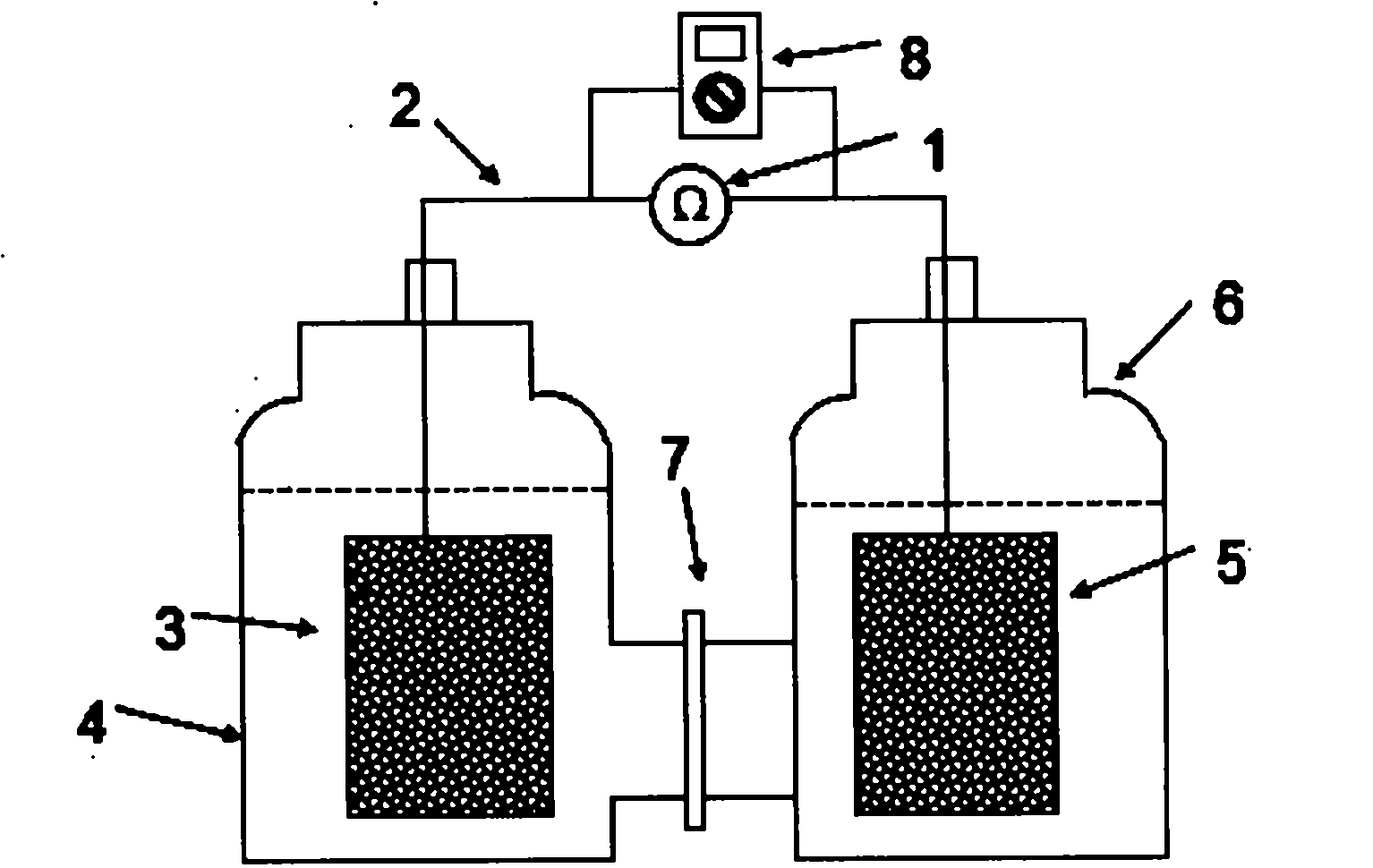
[0021] Step 1: Build a microbial fuel cell, such as figure 1 As shown: the anode chamber 4 and the cathode chamber 6 are made of glass, with a volume of 250 ml, separated by a Nafion 112 selective proton permeable membrane 7 .

[0022] Step 2: Put the anode electrode 3 and the cathode electrode 5 into the anode chamber 4 and the cathode chamber 6 respectively, and the electrode material of the anode electrode 3 and the cathode electrode 5 is 2.5×4cm 2Carbon paper (Toray, Japan), connect the anode electrode 3 and the cathode electrode 5 through the external circuit wire 2, connect the external resistance 1 of 1000 ohms to the external circuit wire 2 to reflect the electricity production situation, and connect the multimeter 8 to collect the electricity production data .

[0023] Step 3: Add 200ml of culture solution to the anode chamber and the cathode chamber respectively, and its composition is: improved M9 inorganic salt solution (5.7mmol / L Na 2 HPO 4 12H 2 O, 3.3mmol / L ...

Embodiment 2

[0029] The operation method of this embodiment is basically the same as that of Embodiment 1, except that 0.5 mmol of azo dye amaranth is added into the cathode chamber as an electron acceptor.

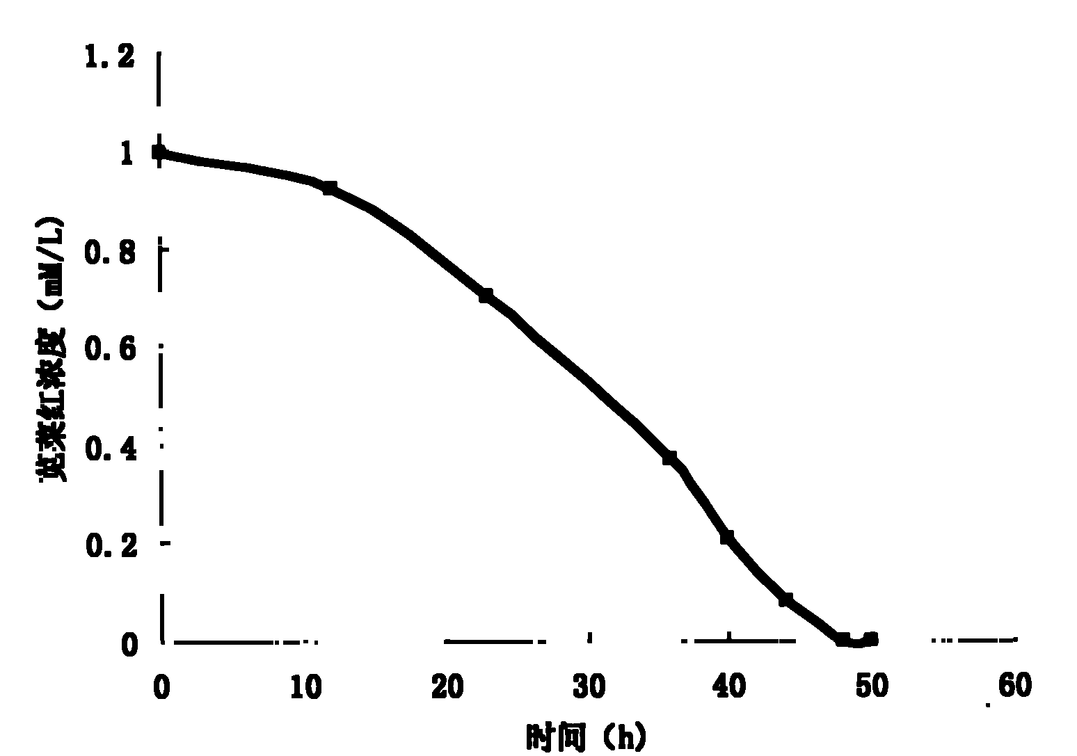
[0030] The results show that: due to the lower concentration of the azo dye as the final electron acceptor in the cathode, the highest output voltage of MFC is 3mV. At the same time, due to the low concentration of the azo dye, the decolorization reaction is completed in a short time, and it takes about 36 hours to completely reduce the azo dye amaranth.

[0031] The microbial fuel cell of this embodiment does not need to provide an additional external power supply to balance the electrodes in the working device at a fixed potential during the entire process of reducing and degrading the azo dye amaranth, so that the azo dye amaranth can be efficiently and thoroughly degraded. Red is completely restored.


PUM


Abstract

The invention discloses a microbial fuel cell and application thereof to degradation of azo dye pollutants. The microbial fuel cell comprises an anode chamber, a cathode chamber, an anode electrode, a cathode electrode, a proton permeable membrane and an external circuit. Electrochemical active microbes are inoculated in the anode chamber. Culture solution for the microbes, a carbon source and electron donors are also contained in the anode chamber. Cathode reaction liquid is contained in the cathode chamber and consists of Shewanella decolorationis and culture solution thereof. Electron acceptors of the Shewanella decolorationis are also contained in the cathode chamber. The microbial fuel cell oxidizes an organic substrate in the solution through the microbes in the anode chamber, generated electrons are transferred to the anode electrode and the electrons on the anode electrode are transferred to the cathode electrode through the external circuit. In the cathode chamber, the Shewanella decolorationis accepts the electrons on the cathode electrode, grows and metabolizes. The electrons are transferred to end electron acceptors such as the azo dye pollutants through a respiratory chain to reduce and degrade the azo dye pollutants. Therefore, the microbial fuel cell can be used for the treatment of the pollutants.

Description

Technical field: [0001] The invention relates to a microbial fuel cell and its application, in particular to a microbial fuel cell using Shewanella decolorationis as the electron acceptor of the cathode, and its application in degrading azo dye pollutants. Background technique: [0002] Azo dyes are widely used in the industrial fields of textile, printing and dyeing, pharmaceutical and food, and enter the environment with the discharge of wastewater. Since almost all azo dyes are artificially synthesized and have stable chemical properties, they are difficult to degrade in the natural environment. With the discovery of the potential "three-induced" effect of azo dyes and related intermediate products, the degradation of azo dyes has received more and more attention. [0003] Traditional azo dye degradation methods include electrochemical method and microbial anaerobic-aerobic combined degradation method, but each has the disadvantages of high energy consumption, high cost ...

Claims


Application Information

Patent Timeline
Patent Type & Authority Applications(China)
IPC IPC(8): H01M8/06C02F3/28H01M4/86H01M8/16
CPCY02E60/50
Inventor 许玫英杨永刚孙国萍郭俊
Owner GUANGDONG INST OF MICROBIOLOGY GUANGDONG DETECTION CENT OF MICROBIOLOGY
Why Eureka
Try Eureka