Anti-electromagnetic-resistance high-power system power supply

A technology of anti-electromagnetic interference and system power supply, which is applied in the direction of high-efficiency power electronic conversion, output power conversion device, electrical components, etc., can solve the problems of serious high-power system power supply, reduce the efficiency of the whole machine, and unfavorable production, etc., to solve the problem of system Effects of EMI problems, reduction of interference sources, and good application prospects

Inactive Publication Date: 2012-01-11
EFORE (SUZHOU) ELECTRONICS CO LTD
View PDF5 Cites 2 Cited by
  • Summary
  • Abstract
  • Description
  • Claims
  • Application Information

AI Technical Summary

Problems solved by technology

Because all power needs to pass through the inductor in one cycle, the PFC inductor has a large volume, which is not conducive to PCB layout and production; because all power needs to pass through the MOS tube in each cycle, the di / dt is very large, and a 2000W system power supply For example, the di / dt generated per cycle is 24A / 30ns; at the same time, the power conversion adopts a hard-switching DC-DC circuit, and the voltage when the MOS tube is turned off in each cycle is 400V, and the generated dv / dt is 400V / 50ns
Because of the large di / dt and dv / dt, the EMI of the high-power system power supply becomes a serious problem. It is necessary to add multi-stage EMI filters and shielding measures to increase the cost and reduce the efficiency of the whole machine

Method used


Image

  • Anti-electromagnetic-resistance high-power system power supply
  • Anti-electromagnetic-resistance high-power system power supply

Examples


Embodiment Construction

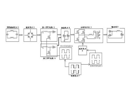
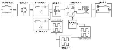
[0015] Such as figure 1 As shown, the anti-electromagnetic interference high-power system power supply includes an EMI filter unit 1, an energy storage unit 4 and a full-bridge soft switch 5. The output end of the EMI filter unit 1 is connected to the rectifier unit 2, the first PFC circuit 3 and the second PFC The circuit 6 is connected to the output end of the rectification unit 2 in parallel, the output end of the first PFC circuit 3 and the output end of the second PFC circuit 6 are connected to the energy storage unit 4, and the energy storage unit 4 is connected to the output through the full-bridge soft switch 5 Terminal 9, the frequency shaking unit 7 is connected to the PFC control circuit 10, the PFC control circuit 10 is connected to the first PFC circuit 3 and the second PFC circuit 6, the frequency shaking unit 7 is also connected to the full bridge control circuit 11, and the full bridge control circuit 11 is connected to the delay unit 8. The delay unit 8 is con...


PUM


Abstract

The invention relates to an anti-electromagnetic-resistance high-power system power supply. The output end of an EMI (Electro Magnetic Interference) filtering unit is connected with a rectifying unit; a first PFC (Power Factor Correction) circuit and a second PFC circuit are connected to the output end of the rectifying unit in a parallel way; the output end of the first PFC circuit and the output end of the second PFC circuit are connected with an energy storage unit; the energy storage unit is connected with the output end through a full-bridge soft switch; a jitter frequency unit is connected with a PFC control circuit; the PFC control circuit is connected with the first PFC circuit and the second PFC circuit; the jitter frequency unit is also connected with a full-bridge control circuit; the full-bridge control circuit is connected with a delay unit; and the delay unit is connected to the full-bridge soft switch. The PFC circuit are set into two paths, so that the current of a power circuit is halved, and di / dt is reduced; the PFC control circuit is provided with the jitter frequency unit, therefore the spectral bandwidth is extended by diffusing the fundamental frequency, the peak energy of the EMI is reduced, the waveform change of the radiation EMI is gentle, the frequency range of EMI filtering is reduced, an EMI filtering circuit is simplified, the EMI inductance value is reduced and the overall efficiency is improved.

Description

technical field [0001] The invention relates to an anti-electromagnetic interference high-power system power supply. Background technique [0002] At present, most of the high-power system power supply circuit adopts a single-channel PFC circuit. The mains input passes through an EMI (electromagnetic interference) filter, and is converted into a half-wave through a rectifier bridge. The BOOST is raised to about 400V through the PFC circuit. The output of the PFC circuit It is an energy storage capacitor, and then converted to the DC voltage required by the user through a first-stage DC-DC circuit. [0003] The traditional PFC circuit consists of an inductor, a MOS tube and a diode. Because all power needs to pass through the inductor in one cycle, the PFC inductor has a large volume, which is not conducive to PCB layout and production; because all power needs to pass through the MOS tube in each cycle, the di / dt is very large, and a 2000W system power supply For example, ...

Claims


Application Information

Patent Timeline
Patent Type & Authority Applications(China)
IPC IPC(8): H02M1/44H02M1/42
CPCY02B70/126Y02B70/1491Y02B70/10Y02P80/10
Inventor 马化盛林宋荣陈昌林
Owner EFORE (SUZHOU) ELECTRONICS CO LTD
Why Eureka
Try Eureka