Automobile fuel in-tank tube and method of manufacturing same

A manufacturing method, fuel tank technology, applied in the direction of liquid fuel feeder, application, hose, etc., to achieve excellent resistance, inhibit decomposition reaction, and prevent clogging of injectors

Inactive Publication Date: 2012-01-11
TOKAI RUBBER IND LTD
View PDF3 Cites 1 Cited by
  • Summary
  • Abstract
  • Description
  • Claims
  • Application Information

AI Technical Summary

Problems solved by technology

[0004] However, although the above-mentioned tank tube 1 is provided in the above-mentioned state, the resistance to sour gasoline (sour gasoline resistance) generated by the oxidation of th

Method used


Image

  • Automobile fuel in-tank tube and method of manufacturing same
  • Automobile fuel in-tank tube and method of manufacturing same
  • Automobile fuel in-tank tube and method of manufacturing same

Examples


Embodiment 1

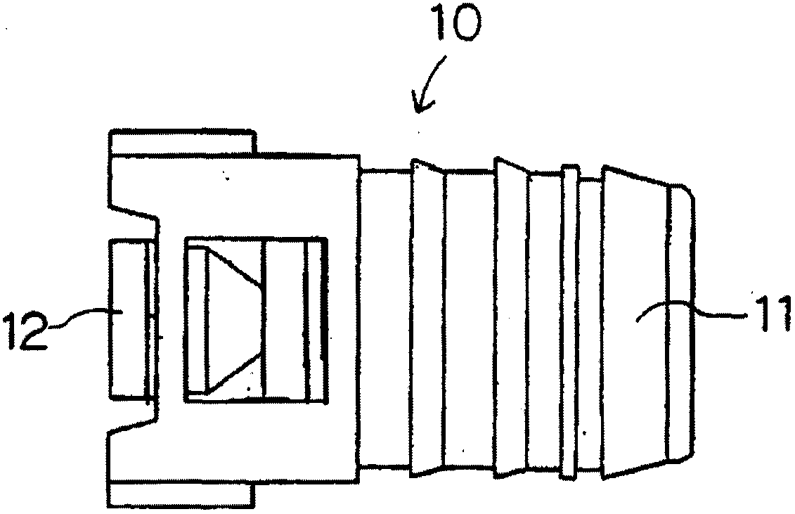
[0067] Aliphatic polyamide resin (I) that is polyamide 11 is extruded into a tube shape (inner diameter: 6mm, outer diameter: 8mm), and then vacuum forming corrugator (vacuum forming corrugator) (manufactured by Japan "Korma" Co., Ltd. , model 120HS) to form a corrugated structure (corrugated structure part: 150mm, outer diameter of valley / peak outer diameter = 7mm / 10mm, pitch length: 3mm) (straight parts at both ends: 10mm, inner diameter of straight parts at both ends: 6mm, Outer diameter: 8mm). Next, it is irradiated with an electron beam (a dose of 250 kGy), and cut into a predetermined length (180 mm in length) by a cutter or the like. Next, put the cut tube into a heat treatment furnace (made by Japan "Espec" company, PV(H)-212), and heat-treat it (150°C x 30 minutes), thereby producing a box-in-box tube (with the above-mentioned inner diameter, outer diameter ).

Embodiment 2~6

[0068] (Examples 2-6, Comparative Examples 1-4)

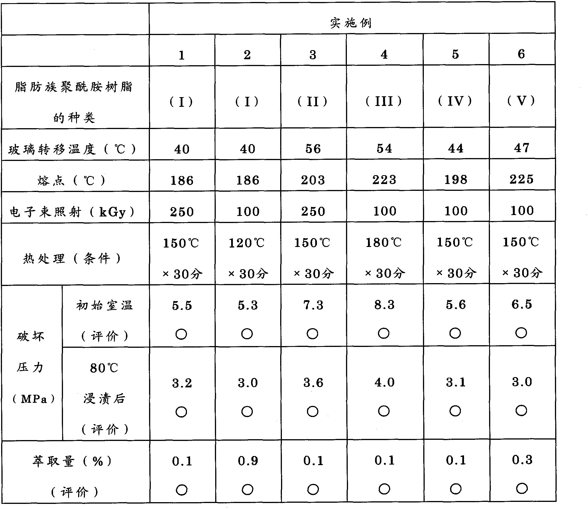
[0069] Inner tubes were produced as in Example 1 except that the type of aliphatic polyamide resin, the conditions of electron beam irradiation and heat treatment, etc. were changed as shown in Tables 1 and 2 below.

[0070] Table 1

[0071]

[0072] Table 2

[0073]

[0074] Using the tank tubes of Examples and Comparative Examples obtained in this way, each property was evaluated according to the following criteria. These results are shown together in Table 1 and Table 2 above.

[0075] (breaking pressure)

[0076] (initial room temperature (23°C))

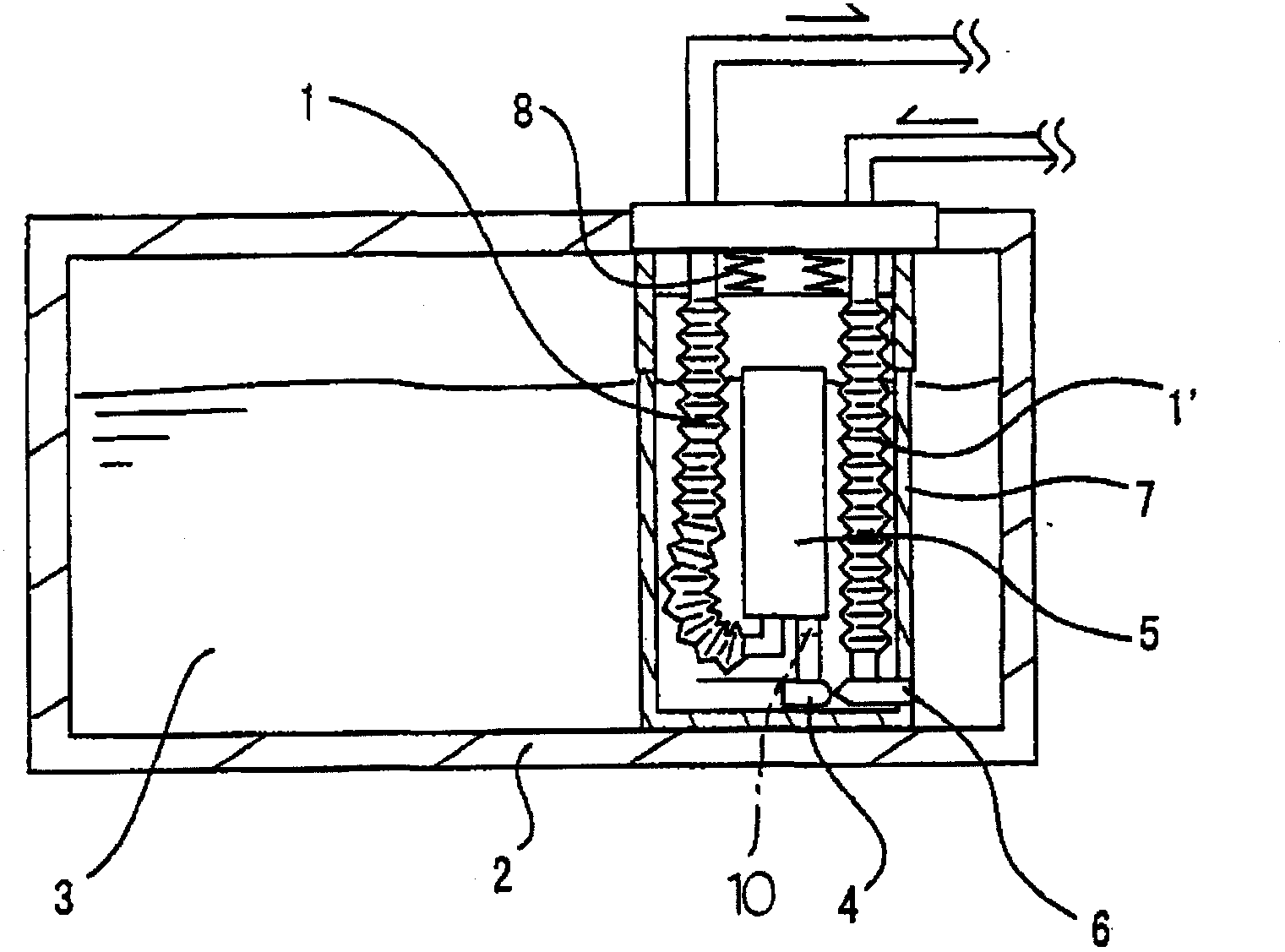
[0077] Fill the tube in the box with silicone oil as a pressurized medium, use the test pipe to plug both ends of the tube in the box, and conduct a pressure test at room temperature (23°C) at a pressure increase rate of 1.0MPa / min to measure the rupture of the tube in the box Or the pressure when the test pipe is disconnected (destroying pressure).

[0078] In the ev...


PUM


Abstract

Disclosed is an in-tank tube with superior pressure resistance performance. A monolayer structure automobile fuel in-tank tube (1) is disposed within a fuel tank (2), and comprises a configuration of absorbing the displacement of the fuel tank (2) and the oscillations of a fuel pump (5). The automobile fuel in-tank tube (1) is formed in a monolayer structure from a resin material, the primary constituent thereof being an aliphatic polyamide resin, said in-tank tube (1) further comprising a pressure-resistant characteristic (X) described hereinafter: (X) The pressure at the time the in-tank tube breaks or comes apart from test pipes, i.e., the breakage pressure, is greater than or equal to 2.8MPa, when the in-tank tube, after immersion in testing fluid [Fuel C: Methanol = 85:15 (based on volume)] for 168 hours at 80 degrees C, is then filled with silicon oil as a pressurizing medium, and a pressure resistance test is carried out at room temperature with both ends of the in-tank tube blocked with the test pipes, at a pressurization speed of 1.0MPa/min.

Description

technical field [0001] The present invention relates to an automotive fuel tank inner pipe (hereinafter referred to as "tank inner pipe" as appropriate) which is arranged in a fuel tank and has a corrugated structure for absorbing displacement of the fuel tank and vibration of a fuel pump, etc. its method of manufacture. Background technique [0002] Generally, in the fuel piping system of an automobile, there is formed a mechanism for extracting and supplying fuel (gasoline, gasohol (gasohol, gasoline plus ethanol), etc.) required for running the engine from the fuel tank at any time. At this time, the above-mentioned fuel is pumped out by a pump (referred to as a fuel pump) which is always located in the fuel tank. Furthermore, in the above-mentioned fuel tank, a hose (hose) connected to the fuel pump is called an in-tank tube, and this hose is always located in the fuel tank similarly to the above-mentioned fuel pump. [0003] it's here, figure 1 The condition inside t...

Claims


Application Information

Patent Timeline
IPC IPC(8): B29D23/00B29C35/02B29C47/00F02M37/00F16L11/11B29K77/00B29L23/18B29C48/09B29C48/13
CPCF02M37/106B29C71/02B29C47/0023B29C35/10B29C2071/022B29L2023/22B29C71/04B29C47/126B29L2031/7172F16L11/111F16L11/15F02M37/0076B29C2035/0877B29C48/09B29C48/303Y10T428/1393B29C48/13
Inventor 片山和孝水谷幸治浅井启太小林德则
Owner TOKAI RUBBER IND LTD
Why Eureka
Try Eureka