Fusion prosthesis

A technology of prosthesis and main body, applied in the field of fusion prosthesis, which can solve problems such as inability to integrate into one body, fatigue fracture, and inconvenience of life for patients

Active Publication Date: 2012-01-18
BEIJING AKEC MEDICAL
View PDF5 Cites 22 Cited by
  • Summary
  • Abstract
  • Description
  • Claims
  • Application Information

AI Technical Summary

Problems solved by technology

[0003] However, the problem existing in the prior art is that continuous pressure is required between the artificial vertebral body and the physiological vertebral bodies of the upper and lower adjacent segments to maintain close contact to prevent the implant from shifting and slipping between the adjacent vertebral bodies, so it must be implanted separately A set of rigid nail-plate or nail-rod system that maintains pressure, and this type of fixation system is usually higher than the original physiological vertebral body surface and has adverse effects on peripheral nerves, blood supply and soft tissue; in addition, the rigid fixation system and The difference in elastic modulus of physiological bone is too large and cannot be fused together, so fatigue fracture is prone to occur in the long run
[0004] In particular, it should be pointed out that some specific stages of vertebral body joints such as the atlantoaxial joint, the atlantoaxial joint is a very special and important vertebral structure connecting the skull and the spine. Conventional cervical artificial vertebral bodies cannot be applied when the axis is missing. At present, there is no targeted prosthesis implantation alternative. In clinical practice, doctors can only temporarily adopt the method of modifying titanium cage or titanium mesh and adding autologous or allogeneic bone according to the specific situation. Bone graft fusion is performed, and it takes a long time after the operation to fix the head, neck and shoulders until complete fusion, which brings great inconvenience to the patient's life

Method used


Image

  • Fusion prosthesis
  • Fusion prosthesis
  • Fusion prosthesis

Examples


Embodiment Construction

[0032] The present invention will be described in detail below with reference to the accompanying drawings and examples.

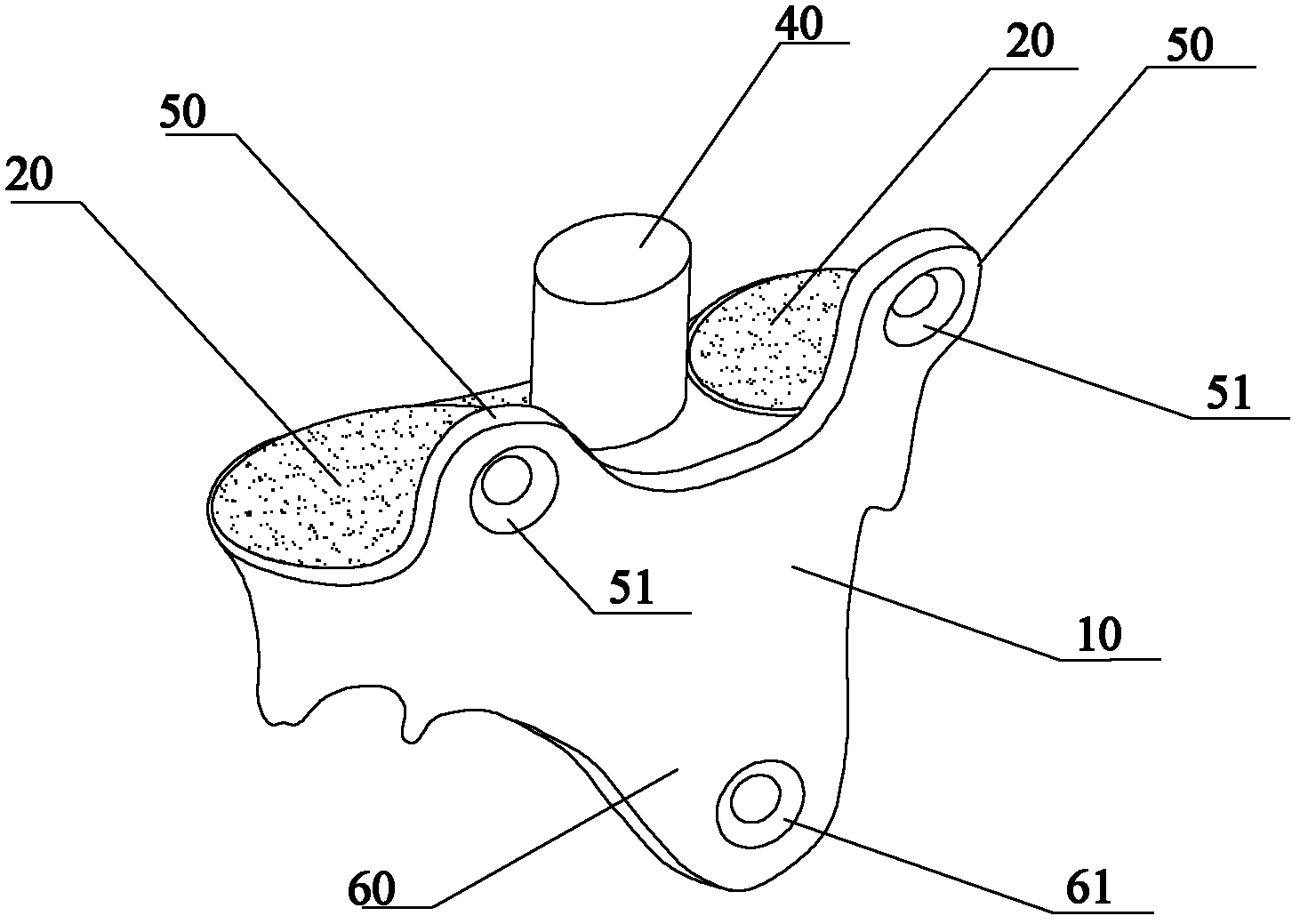
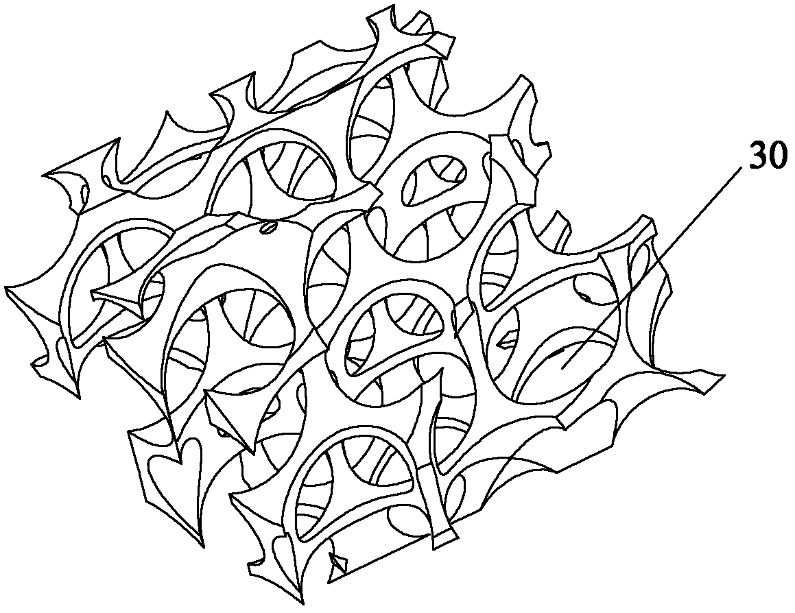
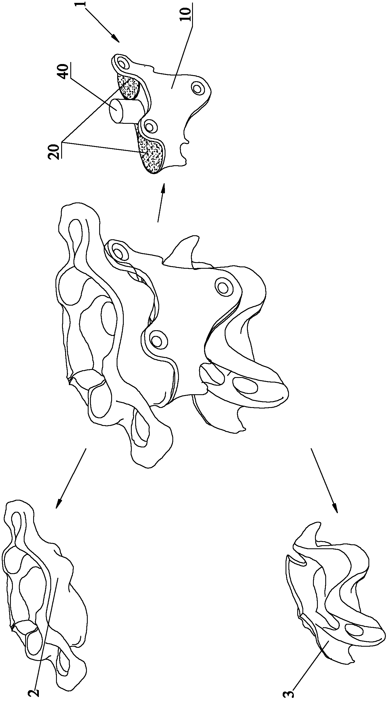
[0033] Such as figure 1 The shown fusion prosthesis according to the present invention is arranged between the first bone structure 2 and the second bone structure 3 to replace the bone structure between the first bone structure 2 and the second bone structure 3, the fusion prosthesis includes a prosthesis Body main body 10 and the prosthesis fusion surface arranged on the prosthesis main body 10, the prosthesis fusion surface fits at least one of the first bone structure 2 and the second bone structure 3, and the surface of the prosthesis fusion surface is slightly Pore ​​structure, the microporous structure is a plurality of interconnected multidirectional micropore structures.

[0034] Adopt fusion prosthesis 1 of the present invention, its prosthesis main body 10 is the equal-sized medical metal implant that makes according to the tomographic data suc...


PUM

PropertyMeasurementUnit
pore sizeaaaaaaaaaa
pore sizeaaaaaaaaaa
diameteraaaaaaaaaa

Abstract

The invention provides a fusion prosthesis. The fusion prosthesis is arranged between a first bone structure and a second bone structure to replace a bone structure between the first bone structure and the second bone structure; the fusion prosthesis comprises a prosthesis main body and a prosthesis fusion surface which is formed on the prosthesis main body; the prosthesis fusion surface is in fit with at least one of the first bone structure and the second bone structure; and the surface of the prosthesis fusion surface has a microcellular structure. The prosthesis main body is an equidimension metal implant which is manufactured according to computed tomography (CT)/ magnetic resonance imaging (MRI)/ ultrasound computed tomography (UCT) and other computed tomography data of a patient, the prosthesis fusion surface is built according to the replaced bone structure and is in fit with at least one of the first bone structure and the second bone structure; the microcellular structure of the surface of the prosthesis fusion surface contributes to crawling and ingrowing of bone cells; and after operation, the prosthesis fusion surface of the fusion prosthesis and at least one bony articular surface of at least one of the first bone structure and the second bone structure are subjected to sacralization so as to achieve long-term stability.

Description

technical field [0001] The invention relates to the field of orthopedic implants, in particular to a fusion prosthesis. Background technique [0002] The spine is the central axis of the human body, the upper part is connected to the occipital bone at the bottom of the skull, and the lower part reaches the end of the coccyx. The spine is connected by the vertebrae, sacrum and coccyx with intervertebral discs, intervertebral joints and many ligaments. It is the activity center of the trunk and the hub of mechanical transmission. It is responsible for supporting body weight, shock absorption, protecting the central nervous system, and providing forward and backward extension of the upper part of the body Flexion, lateral bending, twisting and other motor functions. Due to the changes in modern human lifestyles and the accelerated pace of life, the load on the spine and surrounding tissues has increased, the chance of injury has greatly increased, and the probability of spinal...

Claims


Application Information

Patent Timeline
Patent Type & Authority Applications(China)
IPC IPC(8): A61F2/44
CPCA61F2002/30962A61F2/4455A61F2002/4495A61F2002/30968A61F2/44A61F2002/30578A61F2002/3095A61F2002/30878A61F2002/30787A61F2002/30789A61F2002/30509A61F2002/30507A61F2002/30013A61F2002/3098A61F2002/3097A61F2002/30952A61F2/30A61F2310/00796A61F2310/00023A61F2002/3092A61F2002/30981A61F2310/00011A61F2/4465A61F2002/30838A61F2/3094A61F2002/30011A61F2002/30948F04C2270/041
Inventor 刘忠军
Owner BEIJING AKEC MEDICAL
Why Eureka
Try Eureka