Rainfall information acquiring and metering method and unit, and rainfall meter
A measurement method and information collection technology, applied in rainfall/precipitation meters, measurement devices, meteorology, etc., can solve the problems of high maintenance cost, easy wear and tear of parts, low measurement accuracy, etc., to improve measurement sensitivity and accuracy, Avoid the effect of many parts and high measurement accuracy
- Summary
- Abstract
- Description
- Claims
- Application Information
AI Technical Summary
Problems solved by technology
Method used
Image
Examples
Embodiment 1
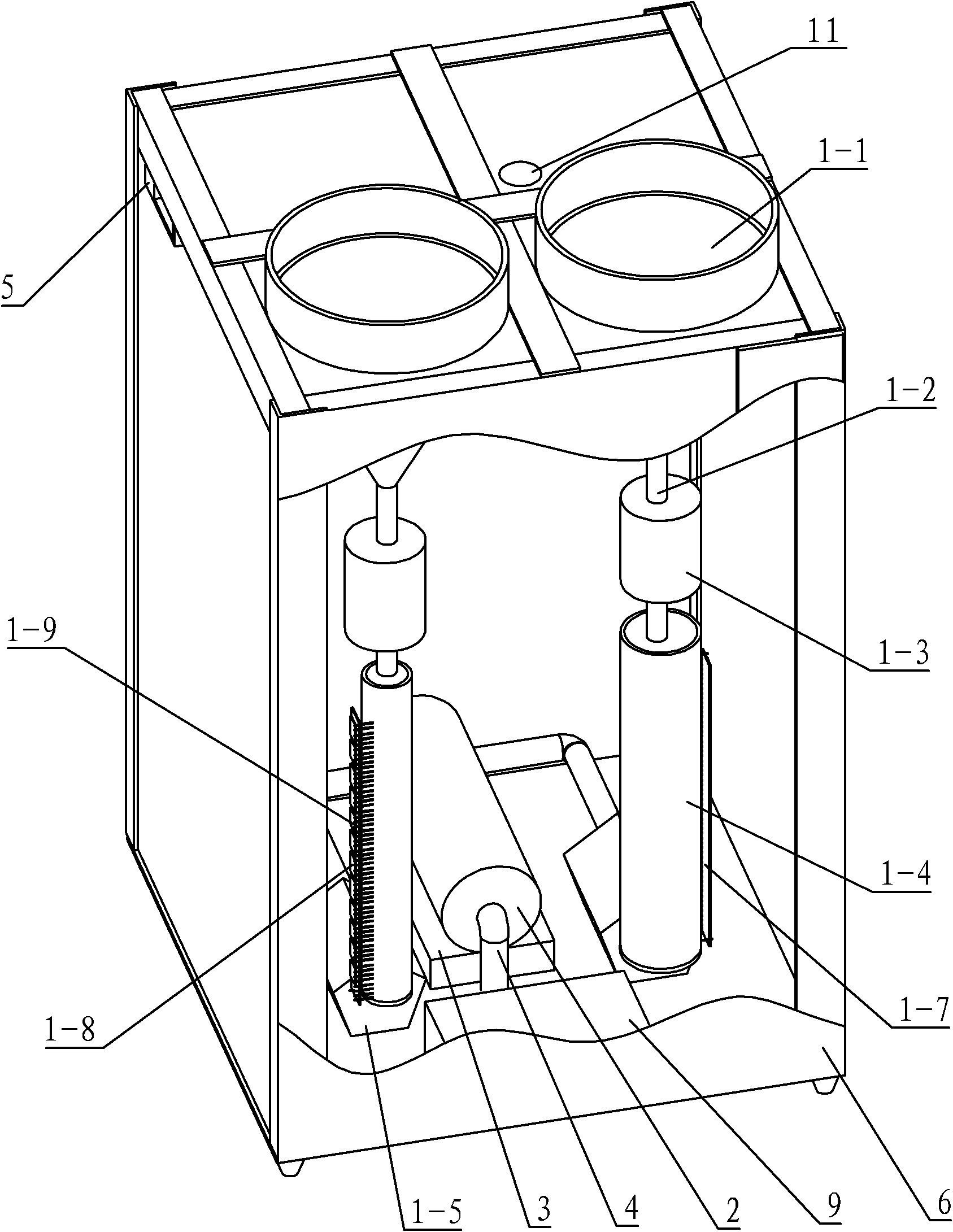
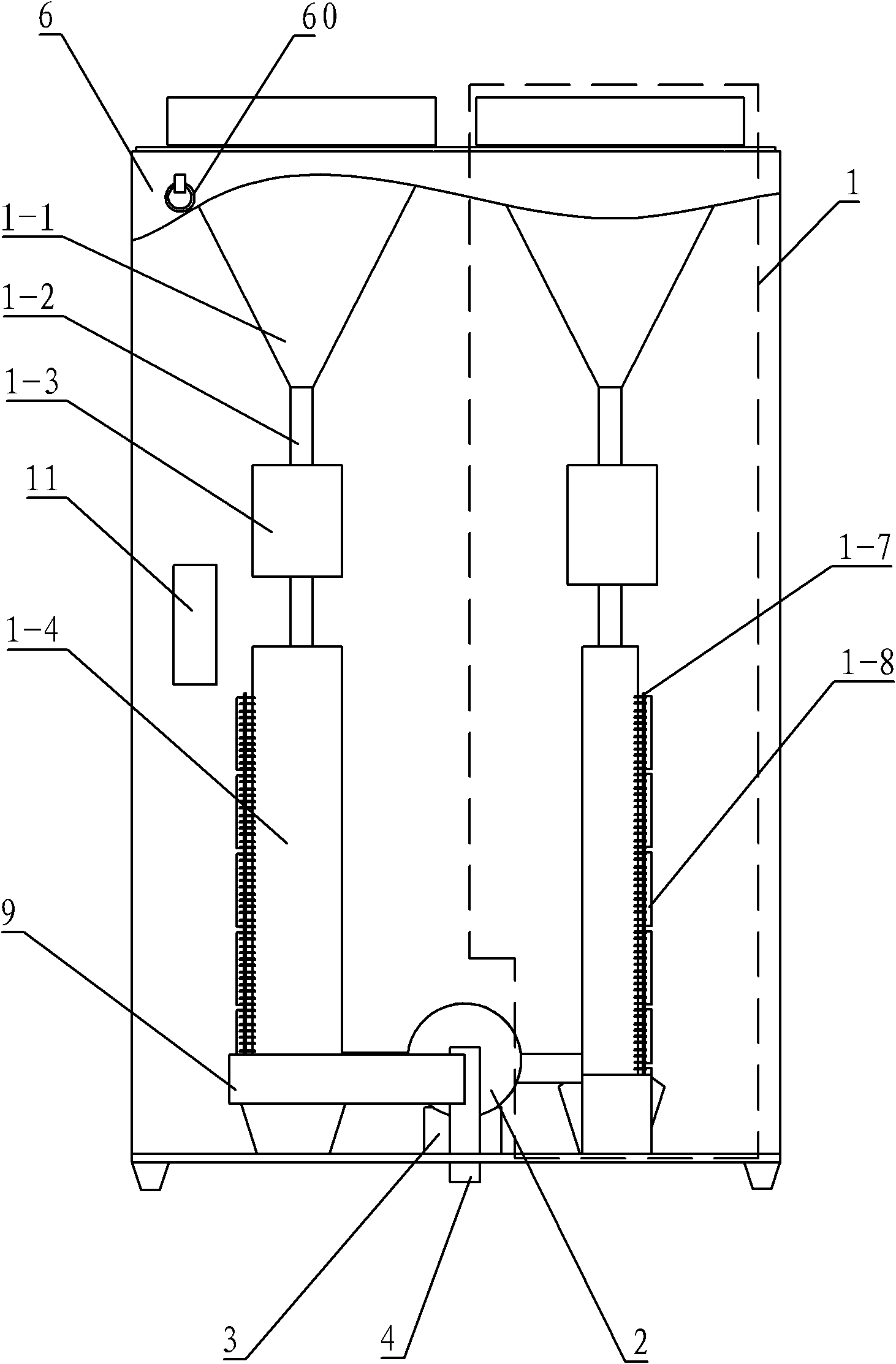
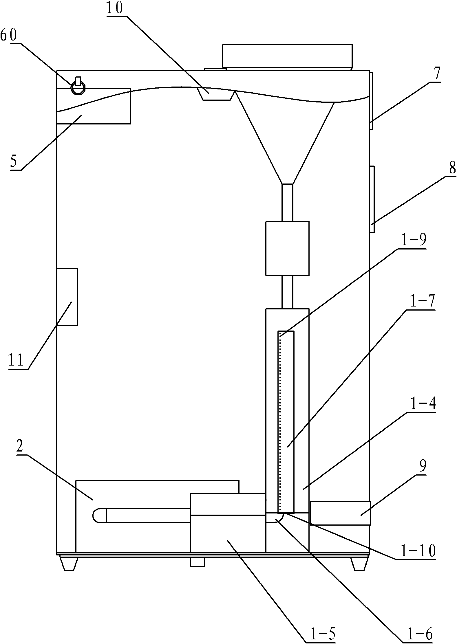
[0044] Such as Figure 1 to Figure 4 As shown, the rain gauge of this embodiment includes a collection and measurement unit 1, a drainage pump 2, a power supply unit 3, a drainage pipe 4, a dehumidification fan 5, a box body 6, an input device 7, a display 8, a controller 9, GSM and GPS antennas 10. Sensor switch 11. Among them, the collection and metering unit 1 is composed of a rain collector 1-1, a water inlet pipe 1-2, a normally open solenoid valve 1-3, a precipitation collector 1-4, a normally closed solenoid valve 1-5, and a pumping pipe 1-6. . The rain gauge of the present embodiment is provided with two sets of collection and measurement units 1, and the capacity of the precipitation collectors 1-4 in each collection and measurement unit 1 is different from each other, being one large and one small. In addition, each set of collection and measurement The components in the unit are basically the same in structure, and in the description of the following embodiments, ...
Embodiment 2
[0066] Such as Figure 5 As shown, the difference between this embodiment and Embodiment 1 is that: from the top view, the water inlet connecting pipe 1-2 is inscribed with the precipitation collector 1-4, that is, the bottom surface circle of the water inlet connecting pipe 1-2 is inscribed with the precipitation collecting device. The top circle of the device 1-4 is inscribed, so that the outlet of the water inlet connecting pipe 1-2 is attached to the inner wall of the precipitation collector 1-4, so that the water flow discharged from the water inlet connecting pipe 1-2 can be attached to the precipitation collector 1 The inner wall of -4 flows down, which can reduce the splash of water and avoid measurement errors.
Embodiment 3
[0068] Such as Figure 6 Shown is a schematic structural diagram of the precipitation collector 1-4 according to Embodiment 2 of the present invention. The difference between this embodiment and Embodiment 1 is that two columns of metering pins 1-9 parallel to each other and vertically arranged are arranged on the metering circuit board 1-7, and the metering pins 1-9 are arranged at equal intervals. The reason for setting the double-column metering pins 1-9 on the metering circuit board 1-7 is: when the rain gauge is placed on an uneven plane, the liquid surface in the precipitation collector 1-4 is not parallel to the horizontal plane, but the liquid surface is inclined When measuring pins 1-9, it is easy to appear that the liquid level actually touched by the metering pins is not the real liquid level, so that there will be deviations. When setting double-column metering pins, the average number of two-column metering pins can be taken when measuring, which can avoid Deviat...
PUM
 Abstract
Description
Claims
Application Information
 - R&D
- Intellectual Property
- Life Sciences
- Materials
- Tech Scout
- Unparalleled Data Quality
- Higher Quality Content
- 60% Fewer Hallucinations
Browse by: Latest US Patents, China's latest patents, Technical Efficacy Thesaurus, Application Domain, Technology Topic, Popular Technical Reports.
© 2025 PatSnap. All rights reserved.Legal|Privacy policy|Modern Slavery Act Transparency Statement|Sitemap|About US| Contact US: help@patsnap.com


