Transresistance amplifier with received signal strength indication (RSSI) function

A technology of received signal strength and transimpedance amplifier, applied in the field of optical communication, can solve the problems of loss, detection of unfavorable optical power, inability to distinguish the size of strong optical power, etc., to achieve high signal-to-noise ratio, elimination of power loss, and clear signal Effect

Inactive Publication Date: 2012-01-18
SUPERXON (CHENGDU) TECH LTD
View PDF5 Cites 18 Cited by
  • Summary
  • Abstract
  • Description
  • Claims
  • Application Information

AI Technical Summary

Problems solved by technology

[0006] The disadvantage of the above technology is: since TIA has requirements on the signal-to-noise ratio of the differential electrical signal, the transimpedance in the current-voltage conversion circuit connected in series with the differential amplifier must have sufficient resistance to achieve the required gain rate
The high gain rate generates a strong current, which eventually causes the RSSI signal output by the TIA to be in a saturated state when the strength of the upstream optical signal is relatively high, making the subsequent optical power detection current unable to distinguish the magnitude of the strong optical power, which cannot meet the accuracy requirements of optical power detection
At the same time, if the inverse data signal is used as the RSSI signal, the additional components of the differential amplifier will also have power loss, which will also cause loss for optical power detection, which is not conducive to the detection of optical power.

Method used


Image

  • Transresistance amplifier with received signal strength indication (RSSI) function
  • Transresistance amplifier with received signal strength indication (RSSI) function
  • Transresistance amplifier with received signal strength indication (RSSI) function

Examples


Embodiment Construction

[0019] All features disclosed in this specification, or steps in all methods or processes disclosed, may be combined in any manner, except for mutually exclusive features and / or steps.

[0020] Any feature disclosed in this specification (including any claims, abstract and drawings), unless specifically stated otherwise, may be replaced by alternative features which are equivalent or serve a similar purpose. That is, unless expressly stated otherwise, each feature is one example only of a series of equivalent or similar features. At the same time, the description of replacement features in this manual is a description of equivalent technical features, and shall not be regarded as a donation to the public.

[0021] If the terms in this specification (including any claims, abstracts and drawings) have both the general meaning and the specific meaning in this field, unless otherwise specified, they are all defined as the specific meaning in this field.

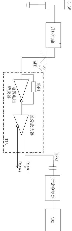
[0022] like figure 1 Sh...


PUM


Abstract

The invention discloses a transresistance amplifier with a received signal strength indication (RSSI) function. The transresistance amplifier is characterized in that an image current source and a second current voltage switching circuit are additionally arranged in an existing transresistance amplifier, so that an image current signal is generated and then converted into an image voltage signal used as an RSSI signal for output, thus the power loss brought by a differential amplifier device is eliminated; simultaneously the transresistance value of the second current voltage switching circuit ranges from 200ohm to 600ohm, thus the condition that the accuracy requirement of optical power detection cannot be met due to RSSI signal saturation caused by overlarge optical power can be prevented; and a BJT (bipolar junction transistor) image current source of a high-speed bandwidth small-signal triode is also used, so that the industrial cost is low while the speed requirement of signal high-speed transmission can be met; and finally the transresistance of a first current voltage switching circuit with a resistance value ranging from 800ohm to 2000ohm ensures that the signal-to-noise ratio of the differential amplifier is higher.

Description

technical field [0001] The invention relates to the field of optical communication, in particular to a device for receiving bursty uplink optical signals and detecting their strength when the passive optical network works in the time-division multiplexing mode. Background technique [0002] The transmission lines used in the traditional communication field are all copper core cables, which have low transmission efficiency and poor anti-electromagnetic interference ability. Due to the characteristics of high transmission efficiency and strong anti-electromagnetic interference ability of optical fiber, with the improvement of communication transmission rate and the improvement of modern manufacturing process, the cost of optical fiber manufacturing has been reduced, and more and more modern communication fields use optical fiber for communication. Transmission of Information. The optical communication network is connected to the access network of the user terminal, and ca...

Claims


Application Information

Patent Timeline
IPC IPC(8): H03F3/08G05F3/26
Inventor 宋岩周健王婧
Owner SUPERXON (CHENGDU) TECH LTD
Why Eureka
Try Eureka