Electro-optical bidirectional tunable finite impulse response (FIR) filter and discrete voltage determination method thereof

A filter and electro-optical technology, applied in the direction of electrical components, impedance networks, digital technology networks, etc., can solve the problems of non-tunable filter networks and low flexibility

Inactive Publication Date: 2012-01-18
TIANJIN UNIV
View PDF5 Cites 11 Cited by
  • Summary
  • Abstract
  • Description
  • Claims
  • Application Information

AI Technical Summary

Problems solved by technology

However, since the target transfer function determines the physical parameters of the network such as cascade series and coupling angle, the filter network is not tunable and the flexibility is not high.

Method used


Image

  • Electro-optical bidirectional tunable finite impulse response (FIR) filter and discrete voltage determination method thereof
  • Electro-optical bidirectional tunable finite impulse response (FIR) filter and discrete voltage determination method thereof
  • Electro-optical bidirectional tunable finite impulse response (FIR) filter and discrete voltage determination method thereof

Examples


Embodiment Construction

[0029] The present invention will be further described below in conjunction with the accompanying drawings.

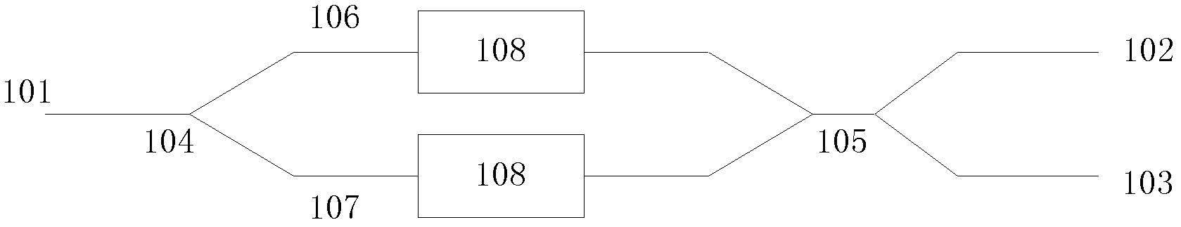
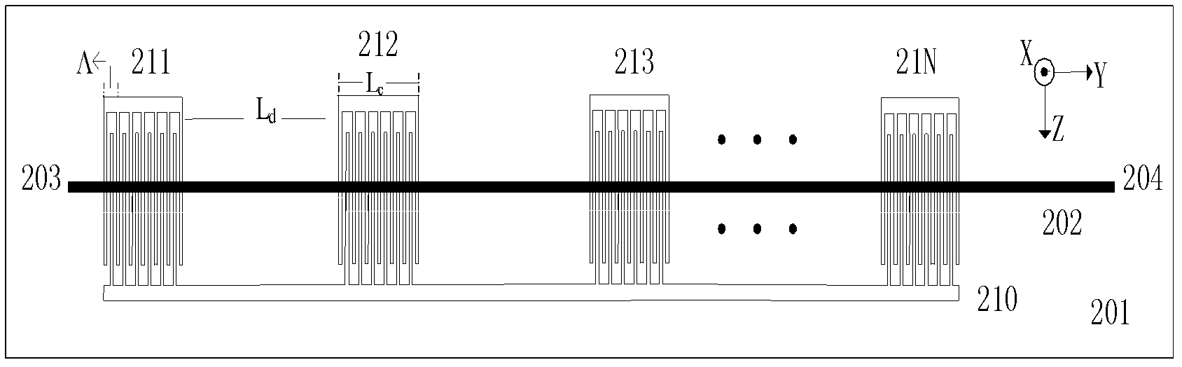
[0030] Such as figure 1 Shown, with λ 0 As the center, the optical signal in the FSR is input from the port 101, passes through the 104 polarization beam splitter, and is divided into two mutually orthogonal polarization modes, the quasi-TE mode and the quasi-TM mode, wherein the quasi-TE mode enters the upper arm polarization-maintaining fiber 106, The quasi-TM mode enters the polarization-maintaining fiber 107 in the lower arm. The signal then enters the polarization conversion unit 108 (i.e. figure 2The unit structure shown), in which the mode conversion occurs, that is, the quasi-TE mode is converted into the quasi-TM mode, and the quasi-TM mode is converted into the quasi-TE mode. The signals are converged at the four-port polarization beam splitter 105, the quasi-TM mode enters the cross waveguide, and the quasi-TE mode enters the straight-through waveguide, ...


PUM


Abstract

The invention relates to the technical field of integrated optical devices and the like, and aims to design a tunable filter for an optical network node, which consists of a polarization beam splitter and a polarization converting unit, wherein the polarization beam splitter is formed by an interdigital electrode group cascade structure which utilizes the N-level periodical distribution controlled by discrete voltages on X-tangent Y-transfer titanium scattered lithium niobate waveguides, the periodical perturbation of the refractive index is generated through regulating all the discrete voltages on the Y direction, so the polarization conversion of a standard TE mode and a standard TM mode is carried out when the wavelengths satisfy the phase matching rule, and the filtering is realized through the polarization beam splitter. The invention simultaneously provides a solving method of the discrete voltage of the filter, so the electro-optical bidirectional finite impulse response (FIR) filtering is realized. The invention has the advantages of quick response speed, high side mode suppression ratio, good rectangular degree and tunable pass band width.

Description

technical field [0001] The invention relates to the technical field of integrated optical devices and the like, and aims to design a tunable filter for optical network nodes. Background technique [0002] Optical filters are widely used in communication systems, mainly including multiplexer / demultiplexer, cross-connector, add / drop multiplexer, dispersion compensation, gain flattening, etc. Among them, tunable filters have become a hot research topic at home and abroad in recent years due to their strong reconfigurability, small insertion loss, simple structure, small size, and low cost. Finding optical filters with fast tuning speed, high precision, flat top of passband, adjustable passband bandwidth and channel spacing is one of the current research priorities. [0003] The current filter tuning technology is mainly based on the acousto-optic effect, electro-optic effect and thermo-optic effect, changing the equivalent refractive index to control the interference and diffr...

Claims


Application Information

Patent Timeline
Patent Type & Authority Applications(China)
IPC IPC(8): H03H17/02
Inventor 金杰刘菲李可佳
Owner TIANJIN UNIV
Why Eureka
Try Eureka