
Hairpin type dual passband electrically-tunable microwave filter
A tuning filter and dual-passband technology, which is applied to waveguide devices, circuits, resonators, etc., can solve the problems of single signal processing frequency band, crowded spectrum resources, and small system capacity, and achieve easy integration and fast tuning speed , low cost effect
- Summary
- Abstract
- Description
- Claims
- Application Information
AI Technical Summary
Problems solved by technology
Method used
Image

Examples
Embodiment 1
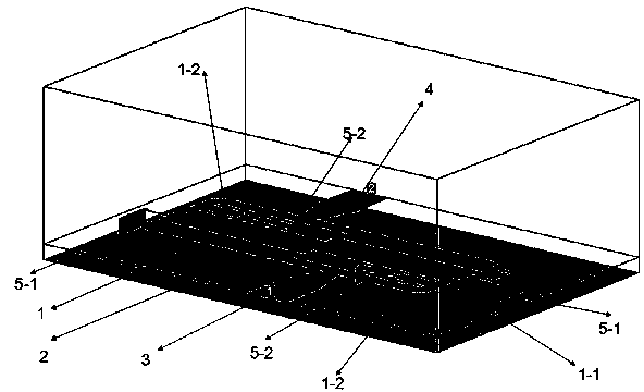
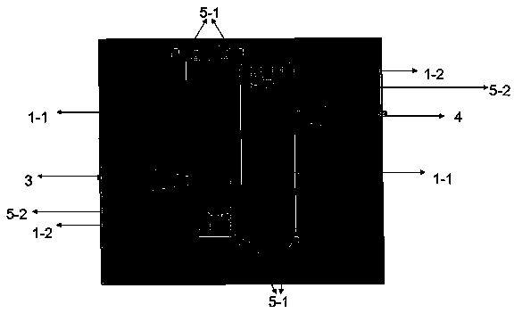
[0030] see figure 1 , The hairpin type dual-passband tunable filter includes a three-layer structure: a metal microstrip line (1) on the front, a dielectric plate layer (2) in the middle and a metal plating layer on the reverse side of the dielectric plate. The metal microstrip line (1) is connected with input and output ports (3, 4) and a ground metal through hole (5). The structure of the metal microstrip line is: a resonator with a symmetrical structure composed of two SIR resonators (1-1) and a central branch (1-2) in the middle of the resonator, so it can be analyzed by odd-even mode theory. A varactor diode D is loaded between the end of the ring double-mode resonator and the grounding metal through hole (5-1), and the center of the open-loop double-mode resonator is short-circuited between the end of the branch (1-2) and the grounding metal through hole (5-2). A capacitor C is added between ) to form a tunable structure.
Embodiment 2
[0032] This embodiment is basically the same as the first embodiment, and the metal microstrip line on the front is such as figure 2 , the special feature is that the open-loop dual-mode resonator is a resonator with a symmetrical structure composed of two SIR resonators (1-1) and a central branch (1-2) in the middle of the resonator. Its structure is symmetrical, resulting in two the resonant frequency of the mode. The SIR resonator adopts a hairpin structure, and the short-circuit branch (1-2) of the resonator can well control the center frequency of the second harmonic. The input and output coupling lines (3, 4) pass through the tapered gradient line When the load voltage is low, an additional limited frequency transmission zero point is added, which improves the attenuation characteristics of the filter. The dielectric plate layer is the dielectric constant The thickness of the dielectric plate is h = 0.8~1.0mm.
Embodiment 3
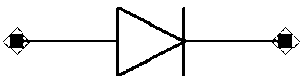
[0034] This embodiment is basically the same as the second embodiment, except that a varactor diode D is loaded between the open-loop dual-mode resonator and the grounded metal through hole (5-1), and the middle central branch (1-2) of the resonator is connected to the Load capacitor C ( image 3 ), load the reverse bias voltage to the varactor diode D through the DC bias circuit, and change the resonant frequency of the odd-even mode to achieve the purpose of adjusting the center frequency and bandwidth of the band-pass filter.
[0035] Figure 4 It is a schematic structural diagram of this embodiment. After design, simulation and optimization, the specific dimensions of the multi-pass band tunable band-pass filter are finally determined as follows:
[0036] L 1 =1.9mm,L 2 =8mm,L 3 =8.6mm, W 0 =2.16mm, W 1 =0.5mm,
[0037] W 2 =1.3mm, S=0.3mm, h=4.6mm, g=0.6mm, d 0 =2.5mm,
[0038] m=0.12mm, t=2mm
[0039] Based on the above method, a dual-pass-band microstrip filt...
PUM
 Abstract
Description
Claims
Application Information