Printing and dyeing sludge pyrolysis treatment device and sludge treatment method

A printing and dyeing sludge and treatment device technology, applied in the field of waste treatment, can solve the problems of industry development constraints, large equipment investment, complex process, etc., and achieve the effects of saving energy, reducing energy consumption, and improving pyrolysis effect

Inactive Publication Date: 2012-02-08
GUANGZHOU UNIVERSITY
View PDF3 Cites 16 Cited by
  • Summary
  • Abstract
  • Description
  • Claims
  • Application Information

AI Technical Summary

Problems solved by technology

However, the current pyrolysis systems in the prior art are all aimed at municipal sludge, that is, the sludge enters the pyrolysis furnace after being dried, and adopts a double-reactor system, the first reactor is for low-temperature volatilization, and the second reactor is for gas phase The main purpose of the reaction is to produce bio-oil, the process is complicated, the energy consumption is high, and the investment in equipment is relatively large. printing and dyeing sludge
At present, there are no reports about printing and dyeing sludge pyrolysis devices, and the existing printing and dyeing sludge treatment technology has lagged behind seriously, which has restricted and affected the development of the industry

Method used


Image

  • Printing and dyeing sludge pyrolysis treatment device and sludge treatment method
  • Printing and dyeing sludge pyrolysis treatment device and sludge treatment method
  • Printing and dyeing sludge pyrolysis treatment device and sludge treatment method

Examples


Embodiment 1

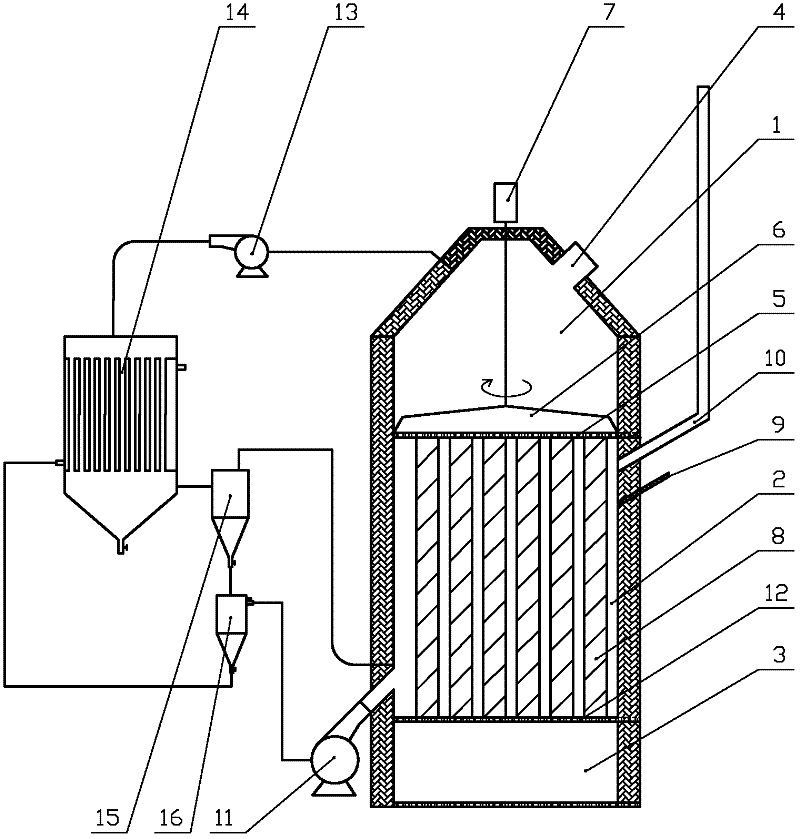
[0034] figure 1 , figure 2 and image 3 Shown is an embodiment of a printing and dyeing sludge pyrolysis treatment device and a sludge treatment method of the present invention. Such as figure 1 and figure 2 As shown, the printing and dyeing sludge pyrolysis treatment device in this embodiment includes a pyrolysis system, waste gas treatment and circulation system.

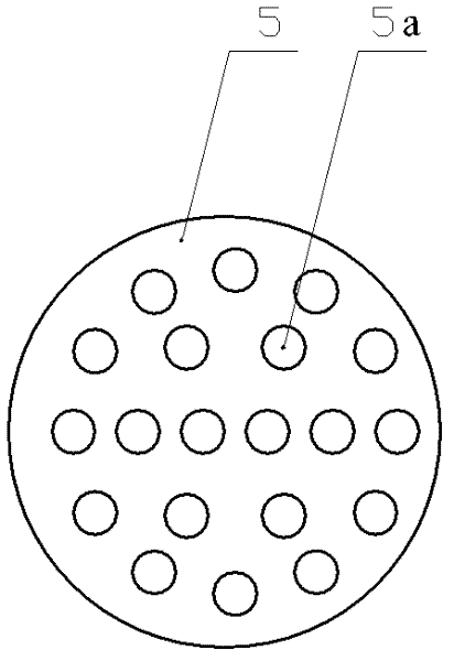
[0035] Such as figure 1 As shown, the pyrolysis system includes a sludge chamber 1, a combustion chamber 2, and a product collection chamber 3 arranged in sequence from top to bottom. Wherein, the sludge chamber 1 is provided with a feed inlet 4, and a support plate 5 with a hole 5a is provided between the sludge chamber 1 and the combustion chamber 2 (see figure 2 ). A rotating plate 6 is arranged above the supporting plate 5 in the sludge chamber 1 and is driven to rotate by a motor 7 . The pyrolysis chamber 8 in the combustion chamber 2 is a plurality of tube-type pyrolysis chambers arranged vertical...

Embodiment 2

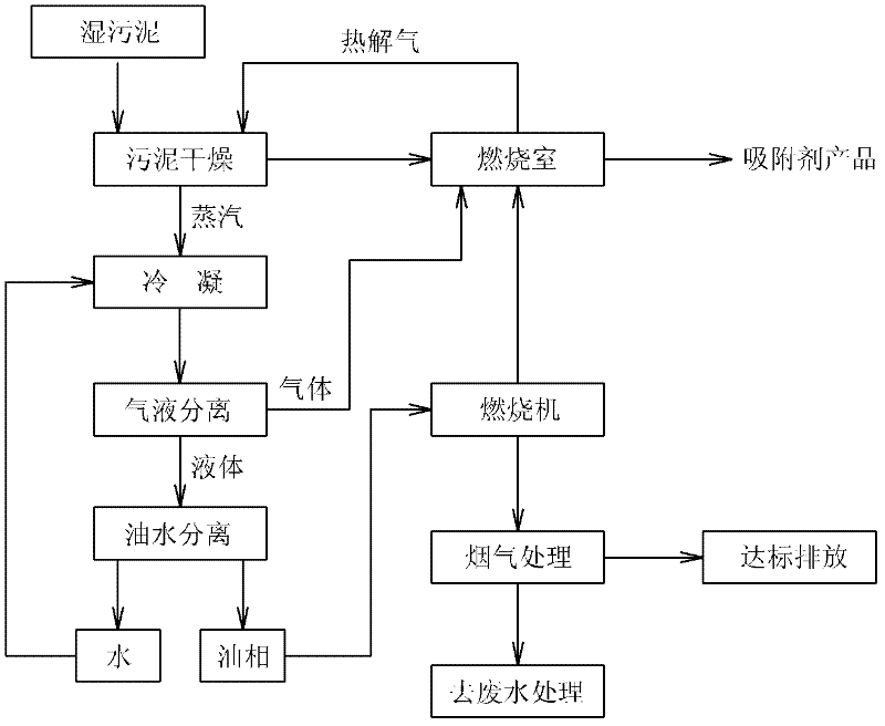
[0047] The difference between this example and Example 1 is: the printing and dyeing sludge pyrolysis treatment method in this example, in step (1-b), the sludge is pyrolyzed at a temperature of 500°C for 10 minutes; in step (2-b) The mixed gas is cooled to 50° C. through the condenser 14 and enters the gas-liquid separator 15 to stay for 1 minute.


PUM


Abstract

The invention discloses a printing and dyeing sludge pyrolysis treatment device which successively comprises a sludge chamber, a combustion chamber and a product collecting chamber from top to bottom, wherein a feed port is arranged on the sludge chamber, and a support plate with holes is arranged between the sludge chamber and the combustion chamber; the combustion chamber is connected with a combustion engine, and a pyrolysis cavity is arranged in the combustion chamber; and a dump valve is arranged between the combustion chamber product collecting chamber. The invention also discloses a printing and dyeing sludge treatment method. In the invention, by adopting the vertical arrangement from top to bottom, the automatic flowing nature of the substance is fully utilized, and the problems of high viscosity and hard feeding of printing and dyeing sludge are solved. Sludge drying, pyrolysis, pyrolysis gas recycling and control are integrated, and energy consumption is effectively reduced. Not only is the recycling of the printing and dyeing sludge realized, but also the harm to environment is greatly lowered. Therefore, the demands of industry development and environmental protection can be well adapted and satisfied.

Description

technical field [0001] The invention relates to the technical field of waste treatment, in particular to a printing and dyeing sludge pyrolysis treatment device and a sludge treatment method. Background technique [0002] With the improvement of people's living standards and the diversification of lifestyles, the rapid development of the clothing industry has also increased the sludge generated in the process of fabric processing, printing and dyeing, which has caused great pressure on environmental protection. Printing and dyeing sludge is different from other ordinary sludge, which is characterized by a large amount of macromolecular organic fibers, residual dyes and inorganic minerals, and high moisture content and high viscosity. At present, most of the existing technologies adopt the disposal method of simple landfill, but the fiber is difficult to degrade, the inorganic minerals are difficult to compress, the landfill pile is unstable, and the heavy metals contained in...

Claims


Application Information

Patent Timeline
Patent Type & Authority Applications(China)
IPC IPC(8): C02F11/10B01D5/00B01D17/02B01D53/78
CPCY02W10/40
Inventor 何国伟范彬刘灵辉朱孟德
Owner GUANGZHOU UNIVERSITY
Why Eureka
Try Eureka