
One-way traveling wave annular cavity single-frequency quasi-three-level solid laser

A solid-state laser, quasi-three-level technology, applied in the laser field, can solve problems such as unfavorable single-frequency laser stable operation, increase system cost and complexity, and influence on laser output performance, so as to reduce adverse effects, reduce cost and complexity , the effect of high degree of linear polarization

Inactive Publication Date: 2013-07-24
TSINGHUA UNIV
View PDF0 Cites 0 Cited by
  • Summary
  • Abstract
  • Description
  • Claims
  • Application Information

AI Technical Summary

Problems solved by technology

At this time, if a multi-channel pumping source is used to pump the gain medium bidirectionally along two propagation paths at the same time, although the problem of reabsorption loss on the two paths with equal propagation lengths can be overcome, it is more difficult to perform bidirectional pumping. The use of one pumping source increases the cost of the system and is not conducive to the stable operation of the single-frequency laser; at the same time, because the output direction of the laser is close to the pumping direction of one of the pumping sources, an additional two-color splitting element must be inserted to separate the pumping direction. Laser and single-frequency output laser, which further increases the cost and complexity of the system
Therefore, in order to ensure the compactness and stability of the laser, and reduce the system cost and complexity, a single pumping source can be selected to only pump in one direction along one of the two propagation paths, but no pumping is added at this time There is significant reabsorption loss on another path with equal propagation length, which will seriously affect the output performance of the laser

Method used


Image

  • One-way traveling wave annular cavity single-frequency quasi-three-level solid laser
  • One-way traveling wave annular cavity single-frequency quasi-three-level solid laser
  • One-way traveling wave annular cavity single-frequency quasi-three-level solid laser

Examples


Embodiment 1

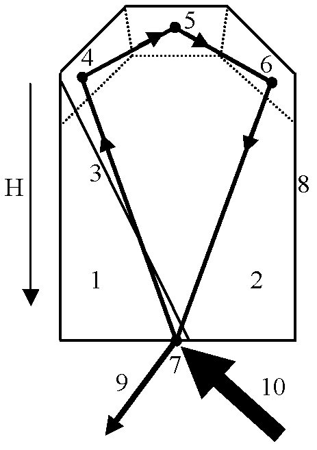
[0015] exist figure 1 In the illustrated embodiment, the ring laser resonator is formed directly from a thermally bonded laser crystal 8 . Applied magnetic field H along figure 1 The direction shown is applied to the thermally bonded laser crystal 8, and the semiconductor laser pumping source 10 is used along the figure 1 The thermally bonded laser crystal 8 is pumped through the end face of the reflection point 7 in the direction shown, and a single-frequency laser output 9 can be obtained at the reflection point 7 .

[0016] Such as figure 1 As shown, the thermally bonded laser crystal 8 is formed by thermal bonding at the interface 3 between an optically isotropic crystal 1 doped with active ions and an optically isotropic crystal 2 not doped with active ions, The crystal 1 doped with active ions is the same as the host crystal of the crystal 2 not doped with active ions, and the host crystal has Faraday magneto-optical properties (for example, a YAG crystal as a host cr...

Embodiment 2

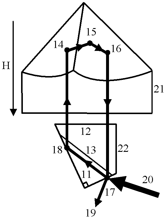
[0023] exist figure 2 In the illustrated embodiment, the ring resonator is composed of two optical elements, a corner cube prism 21 and a thermally bonded laser crystal 22 . The corner cube is an optical element with the characteristic that the direction of the outgoing beam is parallel to the direction of the incident beam, and the corner cube is made of an optical medium (for example, fused silica glass) with Faraday magneto-optical properties. Applied magnetic field H along figure 2 The directions shown apply to the corner cube 21 . Applying an external magnetic field to the corner cube prism 21 not only provides greater freedom in selecting magneto-optical materials, but also facilitates the fixed installation of the magnet, for example, the corner cube prism 21 can be directly placed in the inner ring of the ring magnet . Using semiconductor laser pumping source 20 along figure 2 The thermally bonded laser crystal 22 is pumped through the end face of the reflection...

Embodiment 3

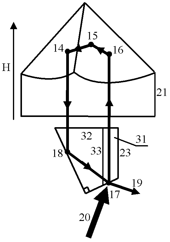
[0031] exist image 3 In the illustrated embodiment, the ring resonator is composed of two optical elements, a corner cube prism 21 and a thermally bonded laser crystal 23 . The corner cube is an optical element with the characteristic that the direction of the outgoing beam is parallel to the direction of the incident beam, and the corner cube is made of an optical medium (for example, fused silica glass) with Faraday magneto-optical properties. . Applied magnetic field H along image 3 The directions shown apply to the corner cube 21 . Applying an external magnetic field to the corner cube prism 21 not only provides greater freedom in selecting magneto-optical materials, but also facilitates the fixed installation of the magnet, for example, the corner cube prism 21 can be directly placed in the inner ring of the ring magnet . Using semiconductor laser pumping source 20 along image 3 The thermally bonded laser crystal 23 is pumped through the end face of the reflection...


PUM


Abstract

The invention discloses a one-way traveling wave annular cavity single-frequency quasi-three-level solid laser. The transmission length of an incident light beam corresponding to reflection in an active ion-doped crystal is smaller than the transmission length of a reflecting light beam in the active ion-doped crystal by using a thermal bonding laser crystal as a laser reflecting element in a cavity and selecting the position of the thermal bonding surface. The one-way traveling wave annular cavity single-frequency quasi-three-level solid laser can reduce the reabsorption loss experienced by laser on an unpumped transmission path when one-way pumping is adopted, thereby ensuring the compactness and stability of the laser, reducing the cost and complexity of the system and effectively improving the laser output performance during one-way pumping. The high linear polarization degree can be obtained in a resonant cavity further by selecting a simple and compact laser structure and the position of the thermal bonding surface so as to be beneficial to efficiently carrying out intracavity frequency doubling.

Description

technical field [0001] The invention relates to the field of laser technology, in particular to a single-frequency quasi-three-level solid-state laser with a unidirectional traveling wave ring cavity. Background technique [0002] Many important applications require the use of high-performance single-frequency quasi-three-level lasers. For example, the 946nm fundamental frequency light (using Nd:YAG crystal as the laser gain medium) required to generate highly stable single-frequency 473nm blue light for extracavity frequency doubling, coherent Doppler radar and high-resolution spectroscopy 2.01 micron laser (using Tm:YAG crystal as the laser gain medium) and most of the laser spectrum lines of the Yb-doped laser gain medium, etc. [0003] In order to achieve efficient and stable operation of this type of single-frequency quasi-three-level solid-state laser, generally by selecting or designing a suitable laser resonator, the laser can circulate in the resonator along the cl...

Claims


Application Information

Patent Timeline
Patent Type & Authority Patents(China)
IPC IPC(8): H01S3/139H01S3/083
Inventor 巩轲吴克瑛何淑芳霍玉晶
Owner TSINGHUA UNIV
Learn More