Dynamic delay, and phase-frequency detector (PFD) and phase lock loop adopting same

A frequency discriminator, dynamic delay technology, applied in the direction of automatic power control, electrical components, etc., can solve problems such as dead zone, and achieve the effect of removing dead zone, overcoming process deviation, and high practical value

Active Publication Date: 2014-02-19
ZTE CORP
View PDF4 Cites 0 Cited by
  • Summary
  • Abstract
  • Description
  • Claims
  • Application Information

AI Technical Summary

Problems solved by technology

Among them, the biggest problem of the PFD module is the "dead zone" phenomenon; the LPF module cannot make the VCO get a smooth control voltage due to the limitation of the attenuation factor

Method used


Image

  • Dynamic delay, and phase-frequency detector (PFD) and phase lock loop adopting same
  • Dynamic delay, and phase-frequency detector (PFD) and phase lock loop adopting same
  • Dynamic delay, and phase-frequency detector (PFD) and phase lock loop adopting same

Examples


Embodiment Construction

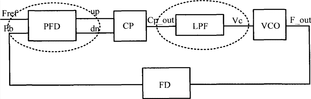
[0032] In this embodiment, a dynamic delayer is used in the PFD of the PLL, which can overcome the PFD dead zone phenomenon caused by the process, temperature, etc. according to the preset delay time; and integrate a resonant circuit in the original passive LPF, which can target the input The frequency of the clock can greatly suppress the stray signal brought in by the input terminal and optimize the system performance.

[0033] The specific implementation will be described in detail below in conjunction with the accompanying drawings.

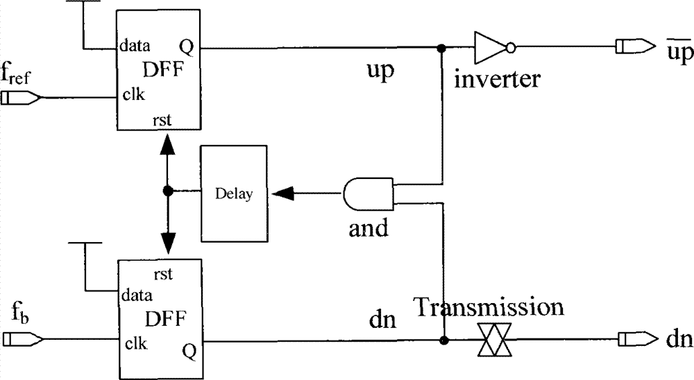
[0034] figure 2 The structure of the existing PFD includes: two flip-flops, a delayer, an AND gate, an inverter and a transmission gate, and the data input terminal (clk) of the first flip-flop is connected to the reference signal f ref , clk of the second flip-flop is connected to the feedback signal f b , the output (Q) end of the first flip-flop is respectively connected to the inverter and one input end of the AND gate, the Q end of th...


PUM


Abstract

The invention discloses a dynamic delay, and a phase-frequency detector (PFD) and a phase lock loop adopting the dynamic delay. The dynamic delay comprises a phase inverter and a plurality of current branches, wherein the grounding end of the phase inverter is respectively connected with one ends of the current branches, one ends of the current branches which are not connected with the phase inverter are grounded, the current branches comprise main current branches and auxiliary current branches, an on-off controller for controlling the on-off state of the circuit is arranged in the auxiliary current branches, the control end of the on-off controller is connected with the output end of the phase reverser, and the output pulse of the phase reverser is used for controlling the state of the on-off controller. The dead region elimination is realized through the practical dynamic control on the PFD reset pulse, the influence caused by process deviation is overcome, the complete consistency of the delay path is realized through the symmetrical NAND gate, and the state after the system lock can be continuously maintained through the adoption of a latch.

Description

technical field [0001] The invention relates to the technical field of integrated circuits, in particular to a dynamic delayer and a frequency and phase detector and a phase-locked loop using the delayer. Background technique [0002] Phase-locked loop (Phase Locked Loop, PLL) is a phase negative feedback control system, which can keep the frequency and phase of the controlled oscillator in a certain relationship with the input signal, and can suppress the noise in the input signal and the voltage-controlled oscillator. phase noise. Such as figure 1 As shown, the currently commonly used PLL is usually composed of a phase frequency detector (Phase Frequency Detector, PFD), a charge pump (Charge Pump, CP), a loop filter (Loop Filter, LPF), a voltage controlled oscillator (Voltage Control Oscillator, VCO) and frequency divider (FrequencyDivider, FD) and other modules of the system. [0003] The standard for measuring PLL performance is the size of the phase noise in the freq...

Claims


Application Information

Patent Timeline
Patent Type & Authority Patents(China)
IPC IPC(8): H03L7/08H03L7/085
Inventor 周滔
Owner ZTE CORP
Why Eureka
Try Eureka