
Double-frequency laser raster interference measuring method and measuring system thereof

A dual-frequency laser and grating interference technology, applied in the direction of measuring devices, optical devices, instruments, etc., can solve the problems that the measurement accuracy has not reached the nanometer level, has not yet reached the nanometer level, and the measurement accuracy is limited, and achieves the stability of the measurement reference Reliable, enhance anti-interference ability and stability, reduce the effect of measurement accuracy

Inactive Publication Date: 2012-02-15
NAT UNIV OF DEFENSE TECH
View PDF4 Cites 36 Cited by
  • Summary
  • Abstract
  • Description
  • Claims
  • Application Information

AI Technical Summary

Problems solved by technology

At present, although grating measuring instruments can obtain high measurement resolution, their measurement accuracy is limited by many factors and has not yet reached the proper nanometer level.
First of all, most grating measuring instruments are a DC signal system, and there is a fundamental problem in the DC system, that is, the trigger level of the counter depends entirely on the output light intensity of the interference system, and the fluctuation of the output light intensity may cause the counter to stop counting , unless the trigger level is readjusted
Secondly, factors such as aging of the laser, beam deflection caused by atmospheric turbulence, deformation of the wave surface, and external vibrations may all cause fluctuations in light intensity.
Especially for faster measurements, it is difficult to track rapid changes in the upper output light intensity, even with automatic adjustments to the trigger level
Therefore, although the existing grating measuring instruments can obtain nanometer-level measurement resolution, the measurement accuracy has not yet reached the nanometer level.

Method used


Image

  • Double-frequency laser raster interference measuring method and measuring system thereof
  • Double-frequency laser raster interference measuring method and measuring system thereof
  • Double-frequency laser raster interference measuring method and measuring system thereof

Examples


Embodiment 1

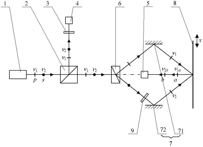
[0029] a kind of like figure 1 Shown is a symmetric incidence dual-frequency laser grating interferometry system based on reflective gratings. The measurement system includes a dual-frequency laser 1 and a first spectroscope 2 for separating the dual-frequency laser output from the dual-frequency laser 1; the dual-frequency laser 1 outputs two orthogonal linear polarization components p and s, and the frequency of the p component for v 1 (also known as v 1 component), the frequency of the s component is v 2 (also known as v 2portion). After the dual-frequency laser output by the dual-frequency laser 1 passes through the first beam splitter 2, a part of it is reflected to form a reference optical path, and the reflected light beam on the reference optical path passes through the analyzer 3 to produce an optical beat phenomenon (the direction of the analyzer 3 and p, s The included angles of the components are all 45°), forming the reference optical path optically shooting ...

Embodiment 2

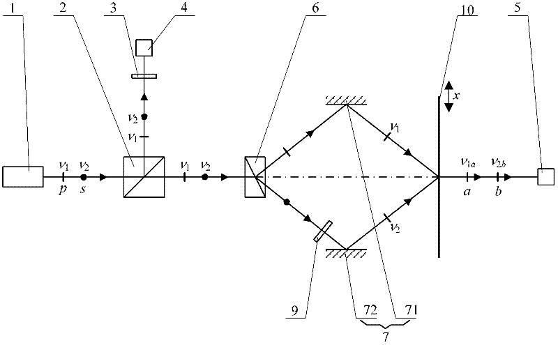
[0031] a kind of like figure 2 The symmetric incidence dual-frequency laser grating interferometry system based on the transmission grating is shown. The measurement system includes a dual-frequency laser 1 and a first spectroscope 2 for separating the dual-frequency laser output from the dual-frequency laser 1; the dual-frequency laser 1 outputs two orthogonal linear polarization components p and s, and the frequency of the p component for v 1 (also known as v 1 component), the frequency of the s component is v 2 (also known as v 2 portion). After the dual-frequency laser output by the dual-frequency laser 1 passes through the first beam splitter 2, a part of it is reflected to form a reference optical path, and the reflected light beam on the reference optical path passes through the analyzer 3 to produce an optical beat phenomenon (the direction of the analyzer 3 and p, s The included angles of the components are all 45°), forming the reference optical path optically ...

Embodiment 3

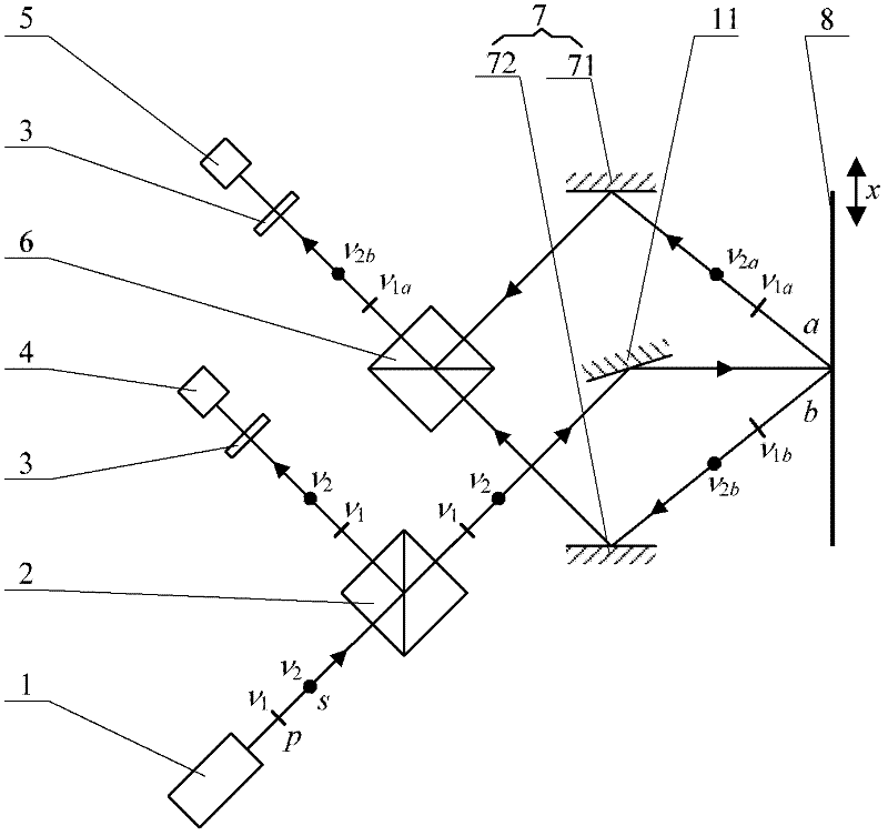
[0033] a kind of like image 3 The vertical incidence dual-frequency laser grating interferometry system based on reflective grating is shown. The measurement system includes a dual-frequency laser 1 and a first spectroscope 2 for separating the dual-frequency laser output from the dual-frequency laser 1; the dual-frequency laser 1 outputs two orthogonal linear polarization components p and s, and the frequency of the p component for v 1 (also known as v 1 component), the frequency of the s component is v 2 (also known as v 2 portion). After the dual-frequency laser output by the dual-frequency laser 1 passes through the first beam splitter 2, a part of it is reflected to form a reference optical path, and the reflected light beam on the reference optical path passes through the analyzer 3 to produce an optical beat phenomenon (the direction of the analyzer 3 and p, s The included angles of the components are all 45°), forming the reference optical path optically shooting...


PUM


Abstract

The invention provides a double-frequency laser raster interference measuring method and a measuring system thereof. The method comprises the following steps: utilizing a double-frequency laser to output double-frequency laser, converting a direct current signal system of common raster interference measurement into an alternating current signal system, allowing the double-frequency laser to go through a spectroscope to form a reference optical path and a measuring optical path, through motion of a raster, allowing beat frequency of measuring optical path optical beat interference fields to change, and finally using a digital phase measuring method to carry out high multiple electrical subdivision on a high multiple optical subdivision signal obtained by each optical beat interference field to complete measurement. The measuring system comprises the double-frequency laser and the first spectroscope, reflected and transmitted light beam go through the first spectroscope and form the reference optical path and the measuring optical path respectively, the reference optical path is provided with a polarization analyzer and a photoelectric detector, the measuring optical path is provided with a raster diffraction interference system, and an output optical path of the raster diffraction interference system is provided with a photoelectric detector. The method and the system have the advantages of strong anti-interference capability, good stability, convenient usage, high measuring precision and the like.

Description

technical field [0001] The invention relates to a measuring method and a measuring system, in particular to a grating interferometric measuring method and a measuring system. Background technique [0002] Nano-measurement is the key technology for the development of advanced manufacturing industry, and also the forerunner and foundation of the entire field of nano-technology. With the development of ultra-precision machining and ultra-fine processing technology, ultra-precision and ultra-fine processing equipment with a stroke of 100 mm and a motion resolution of nano-scale has put forward an urgent demand for large-range, nano-scale high-precision testing methods . Among many nano measuring instruments, grating measuring instruments have the characteristics of large measuring range and high measuring resolution. [0003] The grating measuring instrument combines the absolute measurement within the period of the grating and the incremental measurement outside the period, a...

Claims


Application Information

Patent Timeline
Patent Type & Authority Applications(China)
IPC IPC(8): G01B11/00
Inventor 颜树华王国超杨俊周卫红杨东兴
Owner NAT UNIV OF DEFENSE TECH
Learn More