Design method of high-precision direction-finding array structure

A high-precision direction finding and array structure technology, which is used in direction-determining direction, measuring devices, radio wave measurement systems, etc., can solve problems such as high cost, increasing the effective aperture of the array, and inability to receive signals from large-aperture array elements.

Inactive Publication Date: 2012-02-15
PLA SECOND ARTILLERY ENGINEERING UNIVERSITY
View PDF2 Cites 11 Cited by
  • Summary
  • Abstract
  • Description
  • Claims
  • Application Information

AI Technical Summary

Problems solved by technology

Such an array mainly has the following disadvantages: (1) The mutual coupling effect between the array elements is large, which is not good for the estimation of the direction of arrival; (2) It is difficult to install the array when the array element size is large such as the aperture, and it is impossible to use a large aperture array element to receive more Weak signal; (3) In order to achieve high-precision DOA estimation, the effective aperture of the array needs to be increased, which requires more array elements and is expensive
In order to reduce the number of array elements under large array aperture, non-equidistant linear arrays such as minimum redundancy array, maximum continuous delay array, and minimum gap array have been designed, but the minimum element spacing of these non-equidistant arrays is still half-wavelength, and the spacing of other array elements is an integer multiple of half-wavelength, such an array still cannot overcome the first two deficiencies of the equidistant linear array

Method used


Image

  • Design method of high-precision direction-finding array structure
  • Design method of high-precision direction-finding array structure
  • Design method of high-precision direction-finding array structure

Examples


Embodiment 1

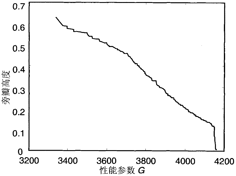
[0064] See Figure 3: According to the array structure design method of the present invention, a series of array structures are designed according to the requirements of Embodiment 1, and then three arrays with different direction finding performances are selected for spatial spectrum estimation, and their performances are compared. Assume that the number of elements of the array to be designed is N=8, and the maximum element position d max =50λ (λ is the signal wavelength), the minimum array element spacing d min =1.5λ, set the maximum number of iterations M, adopt the particle swarm optimization algorithm, and carry out optimal design according to the specific design steps of the present invention. The performance relationship of the optimal result output by step 4 is as follows image 3 shown. In the figure, the performance parameter G obtained in step 3 is the ordinate, and the side lobe height is the abscissa to obtain a graph. According to the array element position d ...

Embodiment 2

[0066] see Figure 3-6 : Carry out simulation experiments to verify the direction finding performance of the designed array: Assume that there are two signals with equal power from two similar directions θ 1 = -45° and θ 2 =-30° incident, the signal-to-noise ratio is 10dB (see formula (1) formula (2)). Adopt the MUSIC algorithm, utilize the three arrays that embodiment 1 designs namely: the array (array 1) with the highest direction-finding accuracy, the array (array 2) with the middle direction-finding accuracy, the worst array (array 3) with direction-finding accuracy by formula (5 ) to estimate the spatial spectrum, the designed array structure is shown in the table below, and the spatial spectra estimated by the three arrays are shown in the attached Figure 3-5 shown.

[0067] Table 1 array structure table

[0068] Array element position

[0069] From the spatial spectra estimated by the three arrays, it can be seen that the false peak of array 1 is relative...

Embodiment 3

[0071] see Figure 7-11 : Test the target resolution success probability, resolution, direction finding deviation and direction finding mean square error performance of the three arrays in Table 1. Assuming that two signals with equal power are incident from two similar directions -45° and -30°, the MUSIC algorithm is used for spatial spectrum estimation, and 1000 independent simulations are performed for each array. If two radiation sources are estimated, and the estimation deviation is not greater than 2°, the algorithm is considered successful, and the successful estimation results are counted. The estimated success rate of each array is attached Figure 6 As shown, the estimated deviation of each array is shown in the appendix Figure 7 , shown in 8, each array estimated mean square error see Figure 9 , as shown in 10.

[0072] It can be seen from this embodiment that, in the case of limiting the minimum array element spacing, the array direction finding accuracy and ...


PUM


Abstract

The invention relates to a design method of an array structure for direction of arrival estimation. The layout of a non-equidistant array is realized through optimizing an array element position. The design method comprises the following several steps: determining minimum array element spacing d<min>, a maximum array element position d<max> and the quantity N of used array elements; calculating an array adjustable array laying-out distance D which is equal to d<max>-(N-1)d<min>; optimally designing an array which is represented by a performance parameter G and a side lobe or a grating lobe height; and outputting an existing optimal result, and the like. By using the design method, through an optimization design, under the condition that the array element spacing is guaranteed to be not less than some specific value, a direction-finding array reaches the optimization between the direction-finding precision and a spatial spectral pseudo peak height; a proper array designed by adopting the method can synchronously realize a lower spatial spectral pseudo peak and the higher direction-finding precision under the condition of fewer array elements; the array element spacing can be enabled to break through half-wavelength limitation, thereby reducing the mutual coupling effect between the array elements and improving the direction-finding precision; a certain space is also preserved for enlarging the apertures of the array elements to detect a weaker signal; and an effective optimization design method is provided.

Description

technical field [0001] The invention belongs to the technical field of transmitting signals that can be detected by a non-directional receiver to determine the relative direction and position of the transmitter, and relates to an array structure design method for Direction of Arrival (DOA) estimation. Background technique [0002] Direction of Arrival (DOA) estimation plays a very important role in electronic countermeasures, underwater acoustic countermeasures and new generation wireless communications. Commonly used DOA estimation methods include interferometer direction finding for a single radiation source and spatial spectrum estimation for multiple radiation sources. These methods are all array-dependent, and the array structure is shown in the appendix figure 1 shown. The interferometer array is generally a non-equidistant array of 3 to 5 elements, and the direction of the radiation source is estimated by deblurring the phase difference when the radiation source num...

Claims


Application Information

Patent Timeline
Patent Type & Authority Applications(China)
IPC IPC(8): G01S3/00
Inventor 刘志强马红光王国华
Owner PLA SECOND ARTILLERY ENGINEERING UNIVERSITY
Why Eureka
Try Eureka