One-key automatic steaming cabinet control system

A technology of control system and rice cooker, applied in the direction of electrical program control, program control in sequence/logic controller, etc., can solve the problems of short circuit, unacceptable, large use current, etc., to achieve accurate operation time and easy maintenance , the effect of simple operation

Inactive Publication Date: 2012-02-15
王栋
View PDF9 Cites 3 Cited by
  • Summary
  • Abstract
  • Description
  • Claims
  • Application Information

AI Technical Summary

Problems solved by technology

[0004] At present, the disadvantages of this technology are: first, the microcomputer controller is installed on the door body, and the inside of the door body can reach 90°C during the steaming process, while the working environment temperature of the general microcomputer cannot exceed 60°C, which greatly shortens the use of the microcomputer Second, the control line connected to the microcomputer is connected to the control terminal through the door hinge. When the door hinge is repeatedly closed, the control line is easily broken, forming an open circuit, and it is not convenient for maintenance; , the general user group is not proficient in the use of microcomputers, which may easily cause microcomputer program disorder; fourth, because the heating tube generally has a large power and uses a relatively large current, experiments have shown that the contacts used in microcomputers are easy to sinter and cause short circuits; fifth, Generally, the transformers of microcomputer controllers are installed here. Once damp or water enters, not only the photoelectric components will be damaged, but the input power of the transformer will also form a short circuit, causing danger; Shorter and higher maintenance costs; microcomputer controllers with higher prices are generally not adopted; Sixth, through market research, the market share of steamed rice cabinets equipped with microcomputer controllers is extremely small, and the repair rate reported by sellers is extremely high

Method used


Image

  • One-key automatic steaming cabinet control system
  • One-key automatic steaming cabinet control system
  • One-key automatic steaming cabinet control system

Examples


Embodiment 1

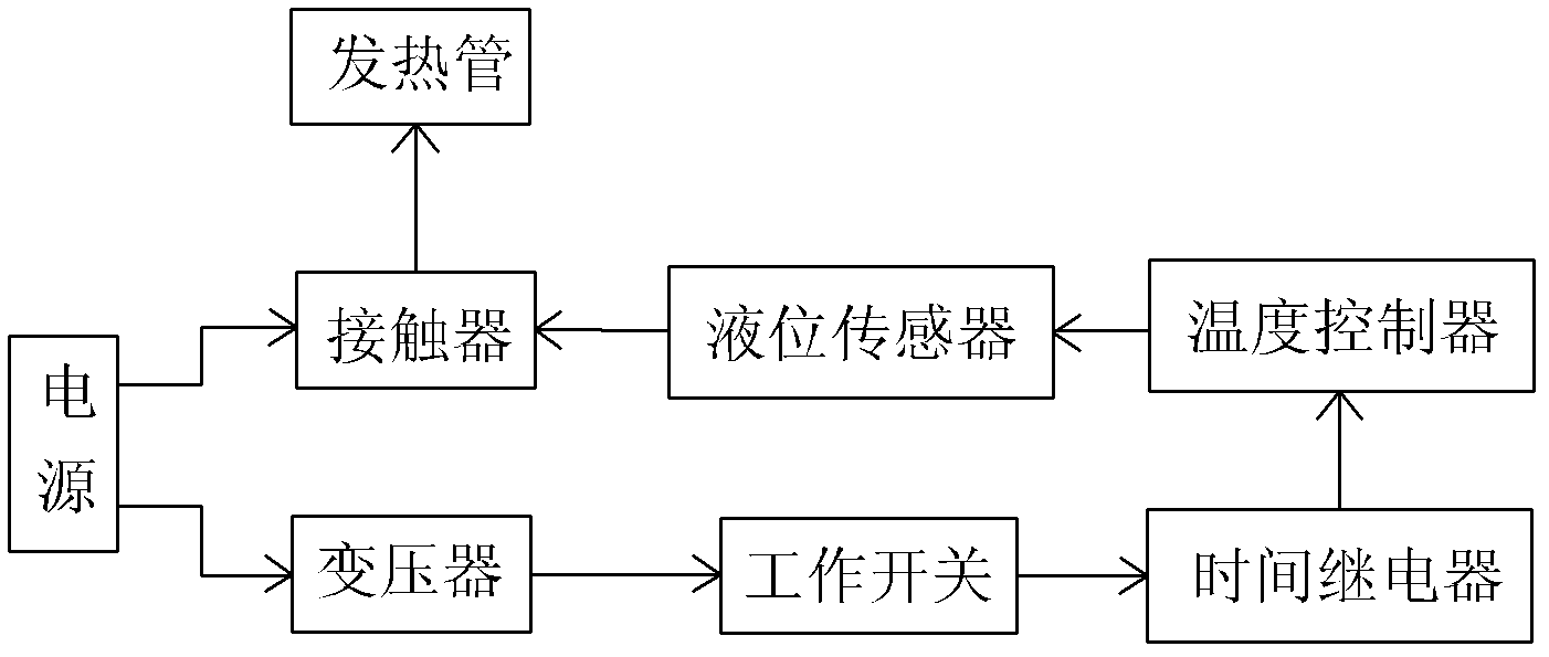
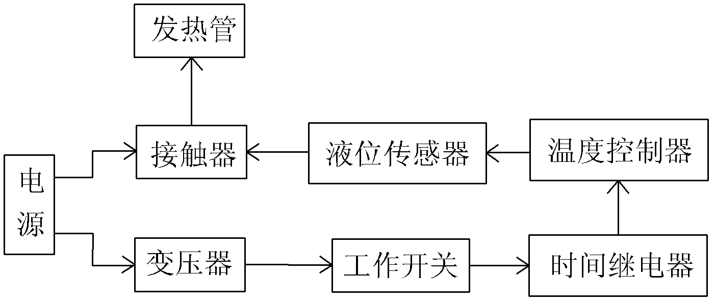
[0019] The power supply is connected to the heating tube through the main contact of the contactor, and the transformer, time relay, temperature controller and button switch are set. The primary side of the transformer is connected to the power supply, and the secondary side of the transformer is connected to the input terminal of the time relay through a series button switch. The time relay The output end of the temperature controller is connected to the control end of the contactor through the temperature controller connected in series, and the signal input end of the temperature controller is connected to the temperature sensor arranged in the rice steaming cabinet.

[0020] The high voltage power is converted into low voltage control power through a transformer when connected to the power supply. By simply closing the button switch, the output voltage of the time relay controls the pull-in of the contactor, the heating tube works to steam rice, and then the time relay accur...

Embodiment 2

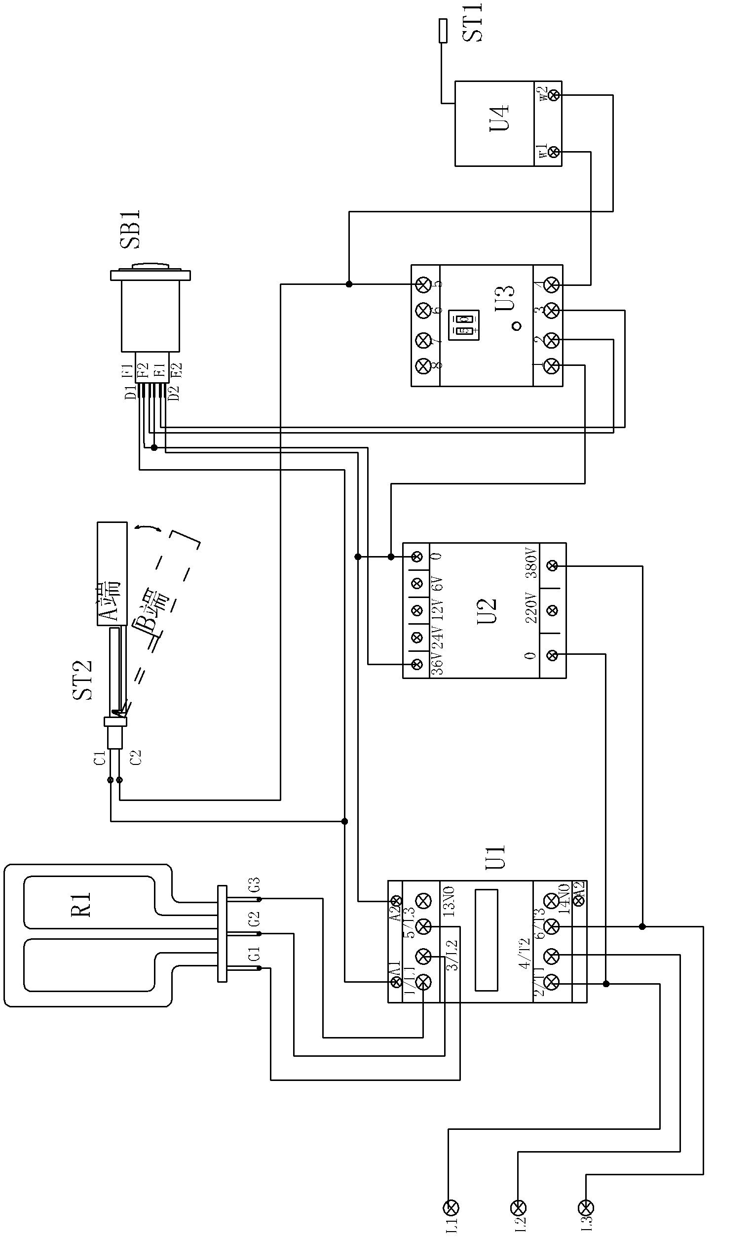
[0023] Such as figure 1 , figure 2 As shown, the power supply L1-L3 is connected to the input terminal G1-G3 of the heating tube through the main contact of the contactor U1, the primary side of the transformer U2 is connected to the power supply, and the secondary side of the transformer U2 is connected to the input of the time relay U3 through the series button switch SB1 The output terminal of the time relay U3 is connected to the control terminal of the contactor U1 through the temperature controller U4 connected in series, and the signal input terminal of the temperature controller U4 is connected to the temperature sensor ST1. The control end of the contactor U1 is connected to a liquid level sensor ST2, and the liquid level sensor ST2 is connected in series with the temperature controller U4. The liquid level switch controls the suction of the contactor of the control line lower than the water level of the heating pipe. After water shortage, the liquid level sensor d...

Embodiment 3

[0025] On the basis of Embodiment 2, the control terminal of the contactor U1 is set to connect to the working status indicator, one input terminal of the working status indicator is connected to the control terminal A1 pin of the contactor U1, and the other input terminal is connected to the secondary side of the transformer U2 the 0V pin. When the control terminal of the contactor U1 is at the working voltage, the indicator light is on, which is used to indicate whether the contactor U1 is working, that is, whether the heating tube L1 is energized and working.


PUM


Abstract

The invention relates to a one-key automatic steaming cabinet control system, belonging to the field of kitchen equipment control. A power supply is connected with a heating pipe through a main contact on a contactor. The one-key automatic steaming cabinet control system is characterized by comprising a transformer, a time relay, a temperature controller and a button switch, the primary side of the transformer is connected with the power supply, the secondary side of the transformer is connected with the input end of the time relay through a serial button switch, the output end of the time relay is connected with the control end of the contactor through the temperature controller connected in series, and the signal input end of the temperature controller is connected with a temperature sensor. High-voltage power can be transformed by the transformer into low-voltage power for control, the time relay outputs the voltage to control actuation of the contactor, the heating pipe works for steaming, the working time of the electric heating pipe is controlled by the time relay, the food temperature is controlled by the temperature controller, the low-voltage short-range control is realized, the operating time is accurate the operation is simple, the water and power are saved, the high-voltage remote control of the conventional steaming cabinet is perfected, and the defects of irregular operating time and dry-burning of the electric heating pipe as a result of water shortage can be overcome.

Description

technical field [0001] The invention provides a one-button automatic rice steaming cabinet control system, which belongs to the field of kitchen equipment control. Background technique [0002] The existing rice steaming cabinet control system generally adopts a power cord to directly access the power supply box or adopts microcomputer control and the like. [0003] Chinese patent ZL 200820022956.1 discloses a fully automatic microcomputer-controlled rice steamer. It has a cabinet, a door is installed on the cabinet, the lower part of the cabinet is a water tank, a control panel is arranged on the door, a microcomputer controller is arranged on the control panel, and the input terminal of the microcomputer controller is connected with the button electric connection, the output end of the microcomputer controller is electrically connected to the input end of the heating control module, the output end of the heating control module is electrically connected to the AC contactor...

Claims


Application Information

Patent Timeline
Patent Type & Authority Applications(China)
IPC IPC(8): G05B19/04
Inventor 王栋
Owner 王栋
Why Eureka
Try Eureka