Ultrathin-wall steel structure connector and connecting structure

A connection structure and ultra-thin-walled technology, which is applied in the direction of building structure and construction, can solve the problems of insufficient research on the new cold-formed thin-walled steel structure system, unfavorable promotion and application, and lack of independent brands, etc., to achieve good axial restraint performance, Simple and fast operation, strong node integrity

Inactive Publication Date: 2012-02-22
河南华斯豪智能科技有限公司
View PDF3 Cites 44 Cited by
  • Summary
  • Abstract
  • Description
  • Claims
  • Application Information

AI Technical Summary

Problems solved by technology

The research on the new cold-formed thin-walled steel structure system is not enough, and they are accustomed to adopting foreign forming technology. The developed structural systems with independent intellectual property rights are very few, and there is a lack of independent brands.
[0006] With the rapid development of new rural construction in recent years, the demand for houses with new structures has continued to grow, and the traditional concept has gradually changed. Steel structure houses have gradually developed in rural areas. The existing steel structure house system is relatively heavy. The construction period is relatively long and the cost is high, which is not conducive to its popularization and application. The inventor applied for a utility model patent for ultra-thin-walled steel structure single profiles and composite profiles and ultra-thin-walled steel structure houses last year. A new type of steel structure housing system, this patent application is to solve the problem of quick installation of the above patent

Method used


Image

  • Ultrathin-wall steel structure connector and connecting structure
  • Ultrathin-wall steel structure connector and connecting structure
  • Ultrathin-wall steel structure connector and connecting structure

Examples


Embodiment 1

[0041] Embodiment 1: An ultra-thin-wall steel structure column connector, which is a cube or a cuboid connector, and the middle part of the two parallel sides of the connector is provided with a hoop groove 3 .

[0042] See the specific structure figure 1 , the front and rear side plates 1 of the connector are two interlocking channel steels (the wing plates of the front and rear side plates can be in contact or not after buckling), and the upper and lower side plates 2 are two interlocking but not in contact channel steel, the upper and lower channel steel flanges 2a and 2b on both sides are fixed on the outer sides of the front and rear channel steel flanges 1a and 1b, wherein the non-contact parts between the upper and lower channel steel flanges form hoop grooves 3.

[0043] In addition, the webs of the front and rear channel steel 1 and the upper and lower channel steel 2 are provided with matching lightening holes.

Embodiment 2

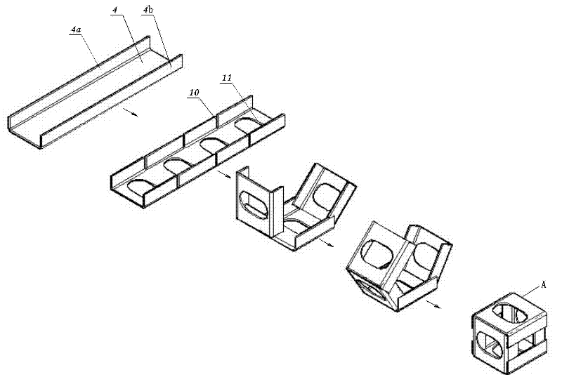
[0044] Embodiment two: see figure 2 , is a folding composition method of the connector described in the first embodiment. The connecting piece is formed by folding a whole strip-shaped channel steel plate 4, and the folding steps are as follows: (1) Make three pairs of groove-shaped grooves 10 respectively on both side symmetrical wing plates 4a and 4b of the strip-shaped channel-shaped steel plate 4 Form four pairs of sub-wings, and meet the requirement that the length of the first and third pair of sub-wings is the same, and the length of the second and fourth pair of sub-wings is the same; at the same time, set matching The lightening hole (2) is folded inwards to form a cube or a cuboid with the straight line where the opposite grooves are located on both sides as the folding edge, and the first and third pair of sub-wings are located on the outside, and the second and fourth pair of sub-wings are located on the inside , the outer and inner sub-wings are respectively fix...

Embodiment 3

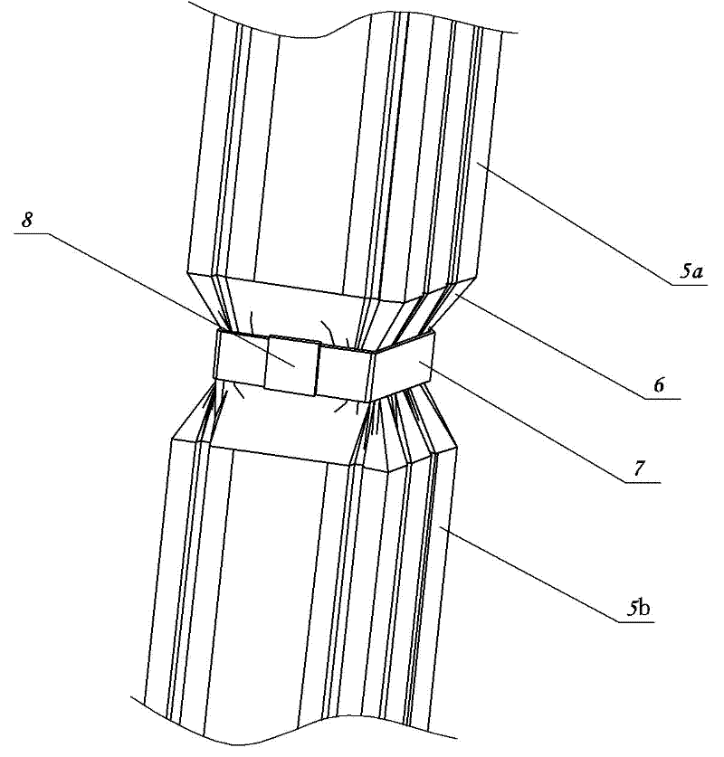
[0045] Embodiment three: see image 3 , a connection structure of an ultra-thin-walled steel column, comprising two hollow ultra-thin-walled steel columns 5a and 5b, the ends of the two hollow ultra-thin-walled steel columns are respectively inserted into the outside of the connector A, and the two sections are hollow The ultra-thin-walled steel column is hooped in the hoop groove 3 of the connector at the same time.

[0046] The width of the clamping steel strip 7 is slightly smaller than the width of the connecting member hoop groove 3 .

[0047] The above connection process is as follows: first use the tightening tool to compress the end of the first hollow ultra-thin-walled steel column 5a to the outside of the connector A hoop groove 3, and then use the tightening tool to compress the end of the second hollow ultra-thin-walled steel column 5b Compress to the outside of the first hollow ultra-thin-walled steel column 5a, set the clamping steel belt 7 on the outside of the...


PUM


Abstract

The invention discloses an ultrathin-wall steel structure connector and an ultrathin-wall steel structure connecting structure. The connector is a hollow square or oblong connector, the front and rear side plates of the connector are two buckled groove type steels, and the upper and lower side plates are two buckled and noncontact groove type steels, wherein two side wing plates of the upper and lower groove type steels are fixed at the outer sides of the front and rear groove type steel wing plates, and a hoop groove is formed at the noncontact part between the upper and lower groove type steel wing plates. The connector is simple, convenient and fast in operation, and has high strength and good axial constraint performance; and the node has strong integrity, local buckling of the end when the ultrathin-wall profile steel is stressed is effectively controlled, and the bearing capacity of a member is improved. The connector has the characteristic of allowing two connecting members in the same direction, and is suitable for mutual butting of two ultrathin-wall profile steels when the ultrathin-wall profile steel members are not long enough. The connector is simple in installation mode, practical and convenient and fast in operation, and the cost and the working time can be greatly saved.

Description

technical field [0001] The invention relates to the technical field of ultra-thin-walled steel structures, in particular to an ultra-thin-walled steel structure connector and its connecting structure. Background technique [0002] The cold-formed thin-walled steel structure building system can adapt to complex building shapes due to its light weight, good seismic performance, and various connection forms. The characteristics of flexible layout, less construction waste, reusable components, and close to zero environmental pollution have attracted more and more attention, and have been listed as preferred projects in low-rise and mid-rise buildings. [0003] With the development of metallurgical technology and the development of cold-formed forming technology, cold-formed steel components are developing towards high-strength and ultra-thin. In the United States, high-strength cold-formed steel with a thickness of 0.55mm-2mm has been widely used in the construction field. my c...

Claims


Application Information

Patent Timeline
Patent Type & Authority Applications(China)
IPC IPC(8): E04B1/58
Inventor 魏群刘尚蔚尚宝平李艳青耿三琳李玥张俊红王镇岳
Owner 河南华斯豪智能科技有限公司
Why Eureka
Try Eureka