Switching power supply circuit

A technology of switching power supply circuit and shut-off control circuit, which is applied in the direction of electrical components, adjusting electric variables, instruments, etc., can solve the problems of high loss of power consumption resistor R1, large power consumption, and failure to meet short-circuit power consumption indicators, and achieve guaranteed Reliability, low output short-circuit power consumption, effect of reducing short-circuit power consumption

Active Publication Date: 2012-02-22
MORNSUN GUANGZHOU SCI & TECH
View PDF1 Cites 70 Cited by
  • Summary
  • Abstract
  • Description
  • Claims
  • Application Information

AI Technical Summary

Problems solved by technology

[0009] but, figure 1 The switching power supply circuit shown has the following disadvantages: when the circuit output is short-circuited, in each switching cycle, when the PWM controller detects that the voltage of its current sampling terminal CS reaches its threshold voltage (UC3843 is 1V), its output terminal OUTPUT immediately Turn off the output of the pulse width modulation voltage signal to prevent the saturation of the main transformer T1 and the overcurrent of the main power tube Qa
Since the auxiliary winding Nt has no output when the output is short-circuited, there is no voltage on the filter capacitor C2, the transistor Q1 will not be turned on, the starting circuit A1 will always work, and the loss on the power dissipation resistor R1 will be very high
Especially in the case of high voltage and wide voltage input, for the auxiliary power supply with an input range of 100V-1000V DC, in order to prevent the start-up extension time at 100V input from being too long, the resistance value of the power consumption resistor R1 should not exceed 100KΩ. In this way, in the case of 1000V input, the loss on the power dissipation resistor R1 will reach In this way, the power consumption resistor R1 must choose a cement resistor with a large volume, and its power consumption is too large (under normal circumstances, the short-circuit power consumption of the auxiliary power supply needs to be controlled at about 1-2W), which does not meet the short-circuit power consumption index when the output is short-circuited. , affecting the reliability of the entire power electronic system

Method used


Image

  • Switching power supply circuit
  • Switching power supply circuit
  • Switching power supply circuit

Examples


Embodiment Construction

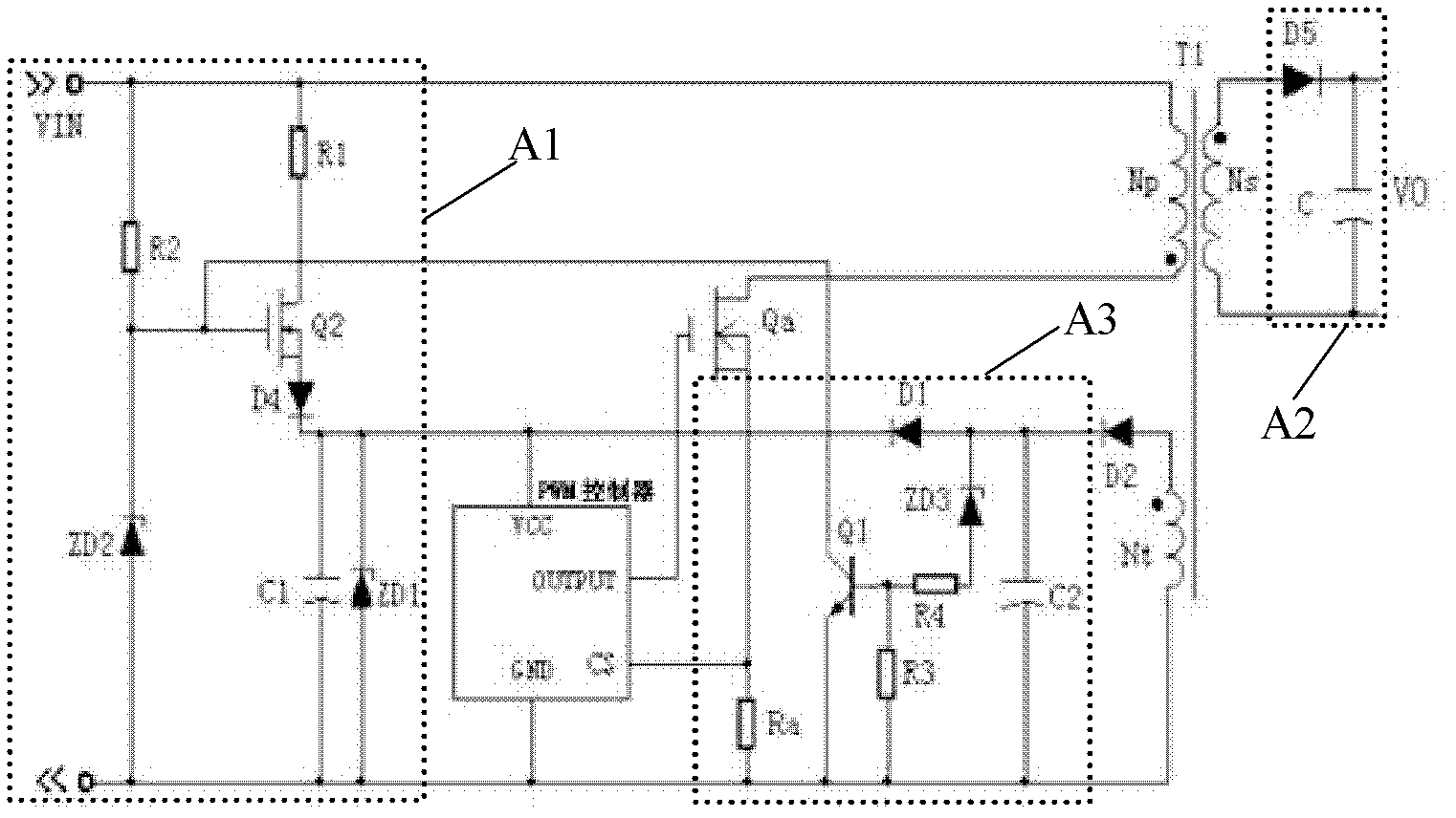
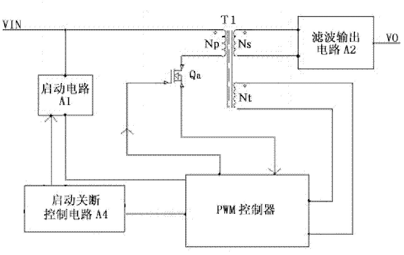
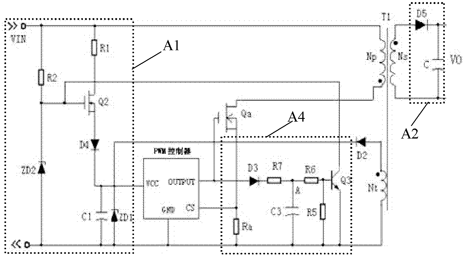
[0025] figure 2 with image 3 The switching power supply circuit of the first embodiment of the present invention is shown, which mainly includes a startup circuit A1, a filter output circuit A2, a startup shutdown control circuit A4, a PWM controller, a main power tube Qa, and a main transformer T1. Among them: start circuit A1, filter output circuit A2, main power tube Qa and main transformer T1 and figure 1 The structural composition and connection relationship of the switching power supply circuit shown are the same, and will not be described one by one here.

[0026] The switching power supply circuit of the first embodiment of the present invention and figure 1 The difference of the switching power supply circuit shown is that the startup and shutdown control circuit A4 includes a first resistor Ra, a first diode D3, a second resistor R7, a shutdown transistor Q3, a charging capacitor C3, a first voltage dividing resistor R5 and The second voltage divider resistor R6; the c...


PUM


Abstract

The invention discloses a switching power supply circuit, which comprises a starting circuit, a pulse width modulation (PWM) controller, a starting turn-off circuit, a main power tube and a main transformer, wherein the starting turn-off circuit comprises a first resistor, a turn-off triode, a charging capacitor, a first voltage sharing resistor and a second voltage sharing resistor; a connection point between the current sampling end of the PWM controller and a source of the main power tube is connected to the voltage reference end of the starting circuit through the first resistor; one circuit of the output end of the PWM controller is connected to the voltage reference end of the starting circuit through the charging capacitor and the other circuit of the output end of the PWM controller is connected to the voltage reference end of the starting circuit through the first voltage sharing resistor and the second voltage sharing resistor sequentially; a connection point between the first voltage sharing resistor and the second voltage sharing resistor is connected to a base of the turn-off triode; a collector of the turn-off triode is connected to the control end of the starting circuit; and an emitter of the turn-off triode is connected to the voltage reference end of the starting circuit.

Description

Technical field [0001] The present invention relates to a switching power supply circuit, in particular to a switching power supply circuit capable of generating small short-circuit power consumption when the output is short-circuited. Background technique [0002] In power electronic systems such as photovoltaic inverters and high-voltage inverters, an auxiliary power supply is required to output low-voltage direct current to supply power to its control part. The power input terminal voltage range of this system is very wide, as low as one or two hundred volts, up to Thousands of volts. For a switching power supply with such a wide input terminal voltage range, its starting circuit is more difficult to design, because it is necessary to take into account the starting time at low voltage input, the starting line loss during normal operation, and the short-circuit power consumption when the output is short-circuited. [0003] Such as figure 1 As shown, in the prior art, a switching...

Claims


Application Information

Patent Timeline
Patent Type & Authority Applications(China)
IPC IPC(8): H02M3/335H02M1/36
Inventor 尹智群余凤兵邓中杰
Owner MORNSUN GUANGZHOU SCI & TECH
Why Eureka
Try Eureka