Three-dimensional modeling apparatus, object, and method of manufacturing an object

A three-dimensional modeling and equipment technology, applied in the direction of processing and manufacturing, manufacturing tools, additive manufacturing, etc., can solve the problem that the lamination accuracy depends on the surface accuracy of the liquid surface, and achieve the effect of improving the flatness

Active Publication Date: 2012-03-14
SONY CORP
View PDF8 Cites 18 Cited by
  • Summary
  • Abstract
  • Description
  • Claims
  • Application Information

AI Technical Summary

Problems solved by technology

In the free surface method, there is a problem that the lamination accuracy of the resin (the thickness accuracy of

Method used


Image

  • Three-dimensional modeling apparatus, object, and method of manufacturing an object
  • Three-dimensional modeling apparatus, object, and method of manufacturing an object
  • Three-dimensional modeling apparatus, object, and method of manufacturing an object

Examples


Example

[0068] [first embodiment]

[0069] (Structure of 3D modeling equipment)

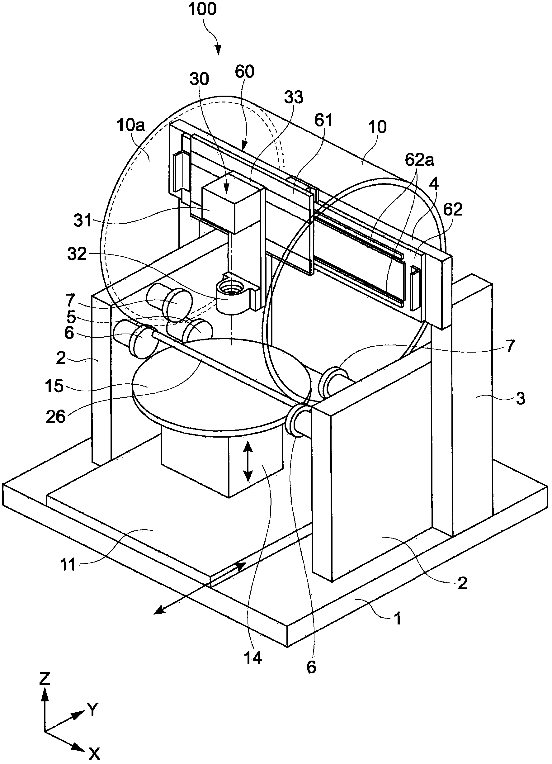
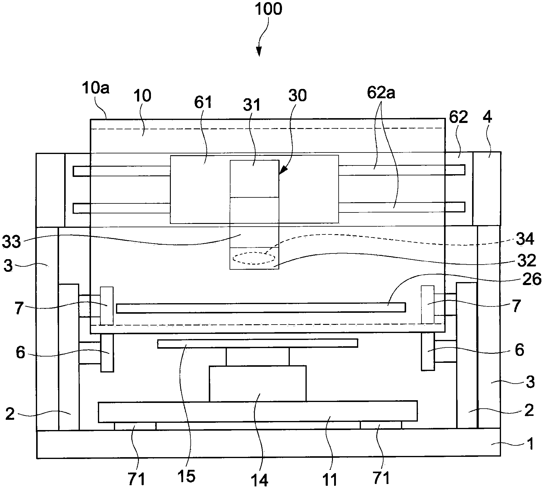
[0070] figure 1 is a perspective view showing a three-dimensional modeling apparatus according to a first embodiment of the present invention. figure 2 is the front view of the three-dimensional modeling equipment viewed along the Y-axis direction.

[0071] The three-dimensional modeling device 100 includes a base body 1 , two side walls 2 , a modeling platform 15 and a drum 10 . The side wall 2 is arranged vertically on the rear side on the base body 1 . A modeling stage 15 is arranged between the side walls 2 . The drum 10 functions as a restraining body, which is arranged opposite to the modeling stage 15 .

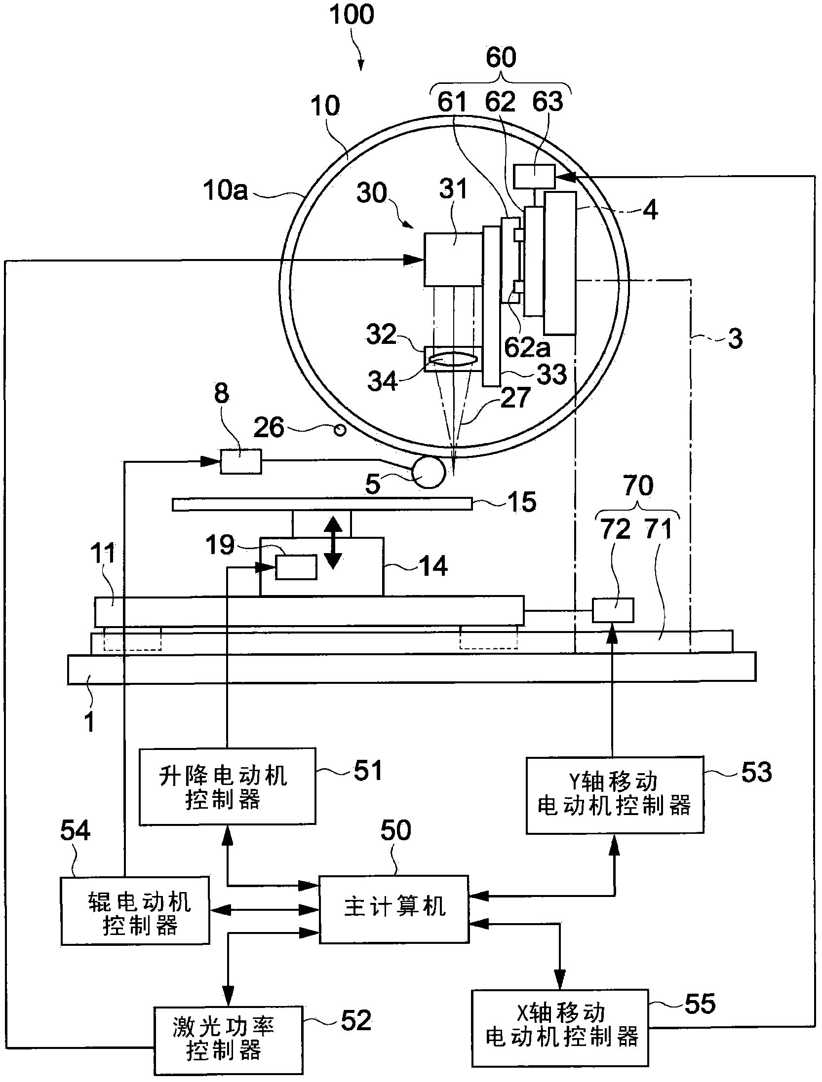
[0072] image 3 is a schematic side view showing the three-dimensional modeling apparatus 100, and a block diagram showing the configuration of a control system therefor.

[0073] As described below, the drum 10 functioning as a restraining body restrains the height of the top surface of...

Example

[0128] [Second embodiment]

[0129] Figure 9 is a side view showing main parts of a three-dimensional modeling apparatus according to a second embodiment of the present invention. Below, the comparison and basis will be simplified or omitted figure 1 In the description of the similar components and functions included in the three-dimensional modeling apparatus 100 of the embodiment shown in ect., differences will be mainly described.

[0130] Instead of the above-mentioned drums acting as restraints, Figure 9 The illustrated three-dimensional modeling apparatus 200 includes a plate member 20 having a surface formed into a curved surface. The plate member 20 is generally part of a cylinder. The plate member 20 includes a lower surface 20a and an upper surface 20b. The lower surface 20a is opposed to the modeling stage 15, and is supported by a plurality of guide rollers 45 and 46, for example. The upper surface 20 b is held by guide rollers 47 . An irradiation unit 30...

Example

[0135] [Third embodiment]

[0136] Figure 10A and Figure 10B They are respectively a side view and a front view of the three-dimensional modeling device according to the third embodiment of the present invention.

[0137] The constrained body of the three-dimensional modeling apparatus 210 according to the present embodiment is a semi-cylindrical body 40 corresponding to a part of the cylindrical body. In other words, each of the semi-cylindrical body 40 and the plate member 20 according to the second embodiment corresponds to a part of a cylindrical body, and has the same function and effect except that the curvature of its outer peripheral surface is different.

[0138] The irradiation unit 80 of the three-dimensional modeling device 210 according to this embodiment includes a laser source 31 and a condenser lens 134 . The condensing lens 134 has a function of condensing laser light. Laser light from the irradiation unit 80 scans the resin liquid R in the X-axis direct...


PUM


Abstract

Provided is a three-dimensional modeling apparatus including a stage, a constraining body, a supply nozzle, an irradiation unit, and a movement mechanism. The constraining body includes a surface including a linear region along a first direction, and is opposed to the stage so that the linear region is the closest to the stage. The supply nozzle supplies a material curable by energy of an energy ray into a slit region between the stage and the linear region. The irradiation unit irradiates the supplied material with the energy ray through the constraining body. The movement mechanism moves the stage relative to the constraining body along a second direction for forming a cured layer of the material for one layer, and moves the constraining body and the stage relative to each other along a stacking direction for stacking the cured layers.

Description

technical field [0001] The present invention relates to a three-dimensional modeling apparatus for forming three-dimensional objects from photocurable materials, to objects formed by the apparatus, and to methods of manufacturing objects. Background technique [0002] In the past, modeling equipment for forming three-dimensional objects has been known as a rapid sample preparation equipment, and it is widely used commercially. Generally, a three-dimensional modeling apparatus forms an object layer by layer based on shape data for each predetermined thickness of the object to be modeled (ie, shape data for each layer). [0003] As one of the main methods for three-dimensional modeling devices, stereolithography is exemplified in which a photocurable resin is selectively irradiated with laser light, whereby a desired part of the resin is cured and drawn, thereby forming an object. [0004] Three-dimensional printing includes, for example, a free surface method and a constrain...

Claims


Application Information

Patent Timeline
IPC IPC(8): B29C67/00
CPCB29C67/00Y10T428/24479B33Y10/00B33Y30/00B29C64/135B29C64/241B29C64/25B29C64/188B29C41/52B29C64/176B29C64/218B29C64/268B29C64/393
Inventor 安河内裕之
Owner SONY CORP
Why Eureka
Try Eureka