Gas burner for premixing automatically-sucked air

A gas burner and pre-mixing technology, applied to gas fuel burners, burners, combustion methods, etc., can solve the problems of low thermal efficiency of burners, reduce production costs, etc., achieve fast combustion speed, reduce production costs, and improve thermal efficiency Effect

Inactive Publication Date: 2012-03-14
金艺
View PDF9 Cites 7 Cited by
  • Summary
  • Abstract
  • Description
  • Claims
  • Application Information

AI Technical Summary

Problems solved by technology

[0003] The purpose of the present invention is to provide a gas burner with automatic air suction and premixing to solve the above problems, solve the problem of low thermal efficiency of the original burner, reduce the auxiliary equipment equipped, and reduce production costs

Method used


Image

  • Gas burner for premixing automatically-sucked air
  • Gas burner for premixing automatically-sucked air

Examples


specific Embodiment approach

[0008] The specific embodiment: the present invention will be further described below in conjunction with accompanying drawing:

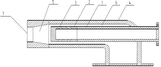
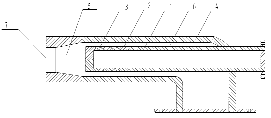
[0009] figure 1 Shown is the structure diagram of the present invention, as shown in the figure, the present invention comprises gas gun tube 1, air pipe 4, and gas gun tube 1 is positioned at the inner center of air tube 4, and front end has gas nozzle 2, and gas nozzle 2 sides are circumferentially provided with spray nozzles. Hole 3. The nozzle hole 3 on the side of the front end of the gas gun tube 1 is an oblique hole, and the oblique hole and the surface of the gas tube 1 form an oblique angle of 10° to 45°, so that the gas ejected from the gas gun tube 1 deviates to the left or right from the centerline of the gas gun tube Rotate around 10°~45° to spray. The annular cavity between the gas gun tube 1 and the air tube 4 is an air passage 6, the inside of the front end of the air tube 4 is tapered, and the space between the front end of the ga...

Embodiment 1

[0013] The present invention is used in Puyang Glass Factory with a furnace of 1.6 million kcal. The pressure of the natural gas raw material is 0.2Mpa, which is the natural pressure from the oil field. It is not additionally equipped with a compressed air, and the wind is natural wind. The natural gas side is used as the power side to design the gas gun barrel, air injection, suction port, gas nozzle and nozzle hole post-processing, installation, and ignition operation. Operation results: The natural gas injection volume of this system is 187 m3 / hour per hour, and the natural gas injection volume of the original system is 200 m3 / hour. Compared with the original system, 6.5% of natural gas can be saved. The air distribution system does not need a blower. While reducing the auxiliary equipment, it can also save electricity by 138 kW × 24 hours × 30 days × 11 months (ie 12 months-1 month maintenance period) = 1092960 kW. The operation process is safe and achieves the expected go...


PUM


Abstract

The invention discloses a gas burner for premixing automatically-sucked air, which comprises a gas-gun pipe and an air pipe, wherein the gas-gun pipe is positioned at the center in the air pipe, the front end of the gas-gun pipe is provided with a gas-spraying head, the circumferential direction on the lateral surface of the gas-spraying head is provided with spraying holes, the annular cavities of the gas-gun pipe and the air pipe are air passages, the front end of the air pipe is provided with a spraying opening, the inner side at the front end of the air pipe is conical, the rear end of the air pipe is provided with a 90-degree right-angle bend, and a premixing chamber is arranged between the spraying holes at the front end of the gas-gun pipe and the air pipe. In the invention, gas after being sprayed out from the gas-gun pipe is rapidly burnt within a short period of time after strengthened premixing is firstly carried out in the premixing chamber, and the gas burner has the advantages of high burning speed, short flame, high temperature, high thermal efficiency and small smoke-gas quantity; and natural wind is used in wind distribution, the gas and air enter by means of respective power, the other party is driven by the power of one party in the entering process, and auxiliary equipment for wind supply does not need to be additionally equipped for the driven party, thereby the production cost is lowered.

Description

technical field [0001] The invention relates to a burner, in particular to a gas burner for natural gas, gas gas and coal gas automatic suction premixing. Background technique [0002] Power plant boilers, various industrial boilers, civil heating boilers, various heating furnaces, various light industrial kilns, and steelmaking furnaces all need burners. Such burners usually use natural gas, gas, and coal gas as fuel. When working, gas and air are sprayed into the furnace from their respective pipes, and burn while mixing. The outlet ends of the gas pipe and the air pipe of this kind of burner are aligned. After the gas and air are sprayed out, they burn at the nozzle. Long, high exhaust gas temperature, low thermal efficiency; in addition, the entire system of gas and air distribution needs to be equipped with auxiliary equipment for air supply. Contents of the invention [0003] The object of the present invention is to provide a gas burner with automatic air suction ...

Claims


Application Information

Patent Timeline
Patent Type & Authority Applications(China)
IPC IPC(8): F23D14/62
Inventor 金艺
Owner 金艺
Why Eureka
Try Eureka