System for taking exhaust gas samples from internal combustion engines

A technology of internal combustion engine and exhaust gas, which is applied in the direction of internal combustion engine testing, sampling, engine testing, etc., and can solve problems such as the inability to use manifold gasoline engines

Active Publication Date: 2012-03-14
AVL EMISSION TEST SYST GMBH
View PDF12 Cites 8 Cited by
  • Summary
  • Abstract
  • Description
  • Claims
  • Application Information

AI Technical Summary

Problems solved by technology

[0007] Although an exhaust gas inspection station is known from DE19505415A1 in which two rolling inspection stations are connected to a single CVS device, however, only the exhaust gas inl...

Method used


Image

  • System for taking exhaust gas samples from internal combustion engines
  • System for taking exhaust gas samples from internal combustion engines
  • System for taking exhaust gas samples from internal combustion engines

Examples


Embodiment Construction

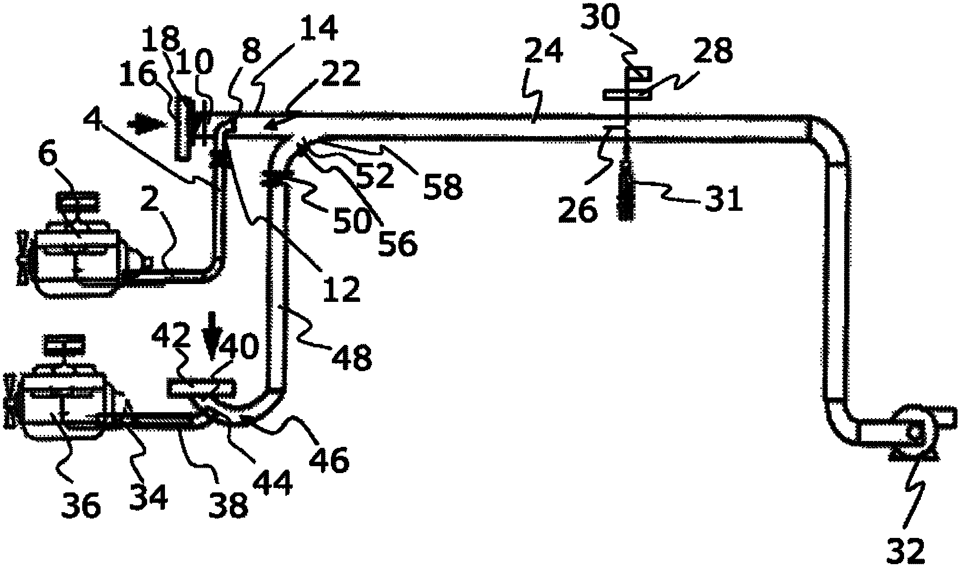
[0023] The device according to the invention for extracting exhaust gas samples from internal combustion engines is used in diesel engines and gasoline engines, the device comprising a first exhaust gas inlet 2, through which a first exhaust gas channel 4 is in fluid communication with an exhaust gas source 6, which The exhaust gas source is constituted by the diesel engine of the motor vehicle.

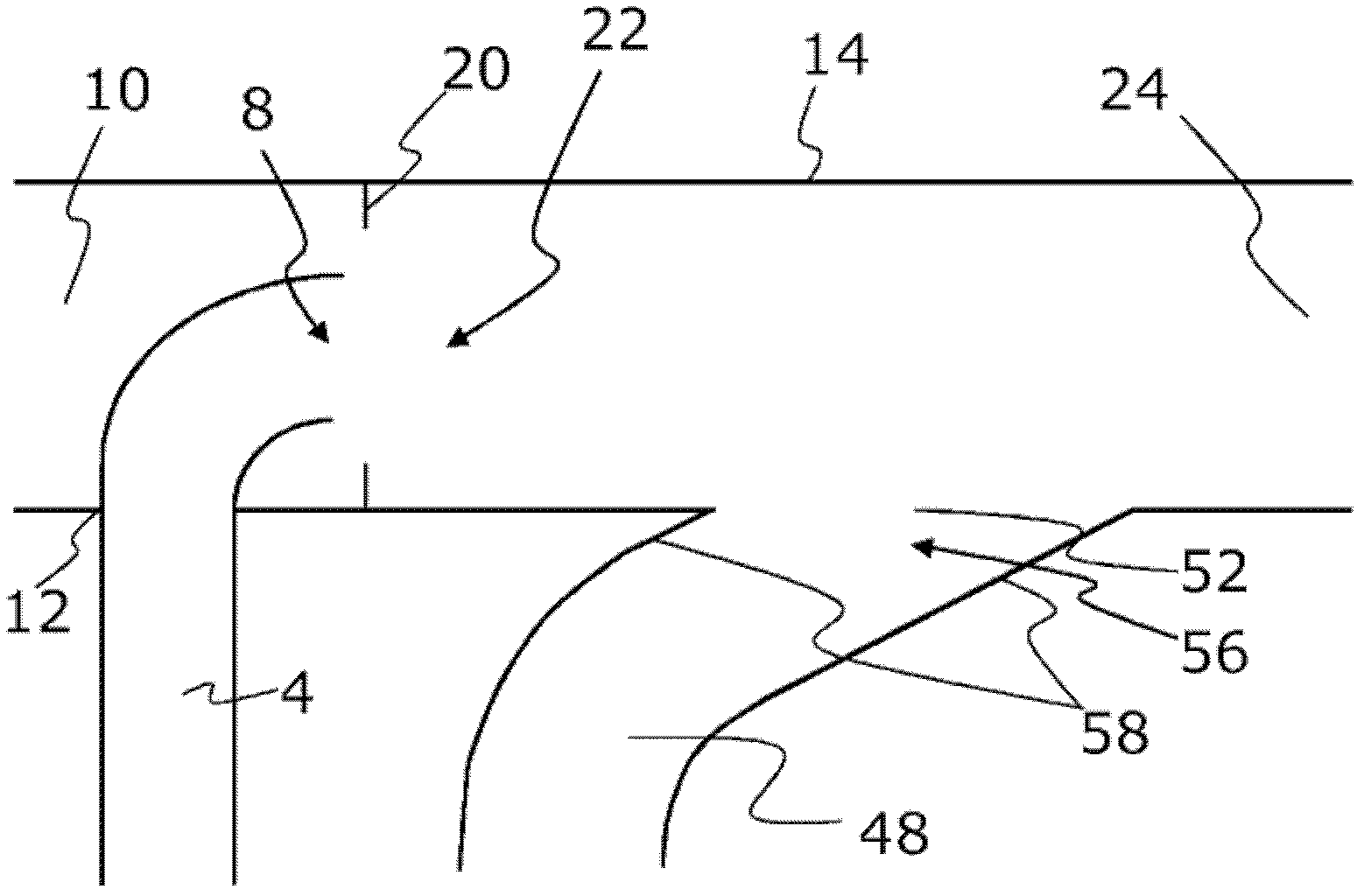
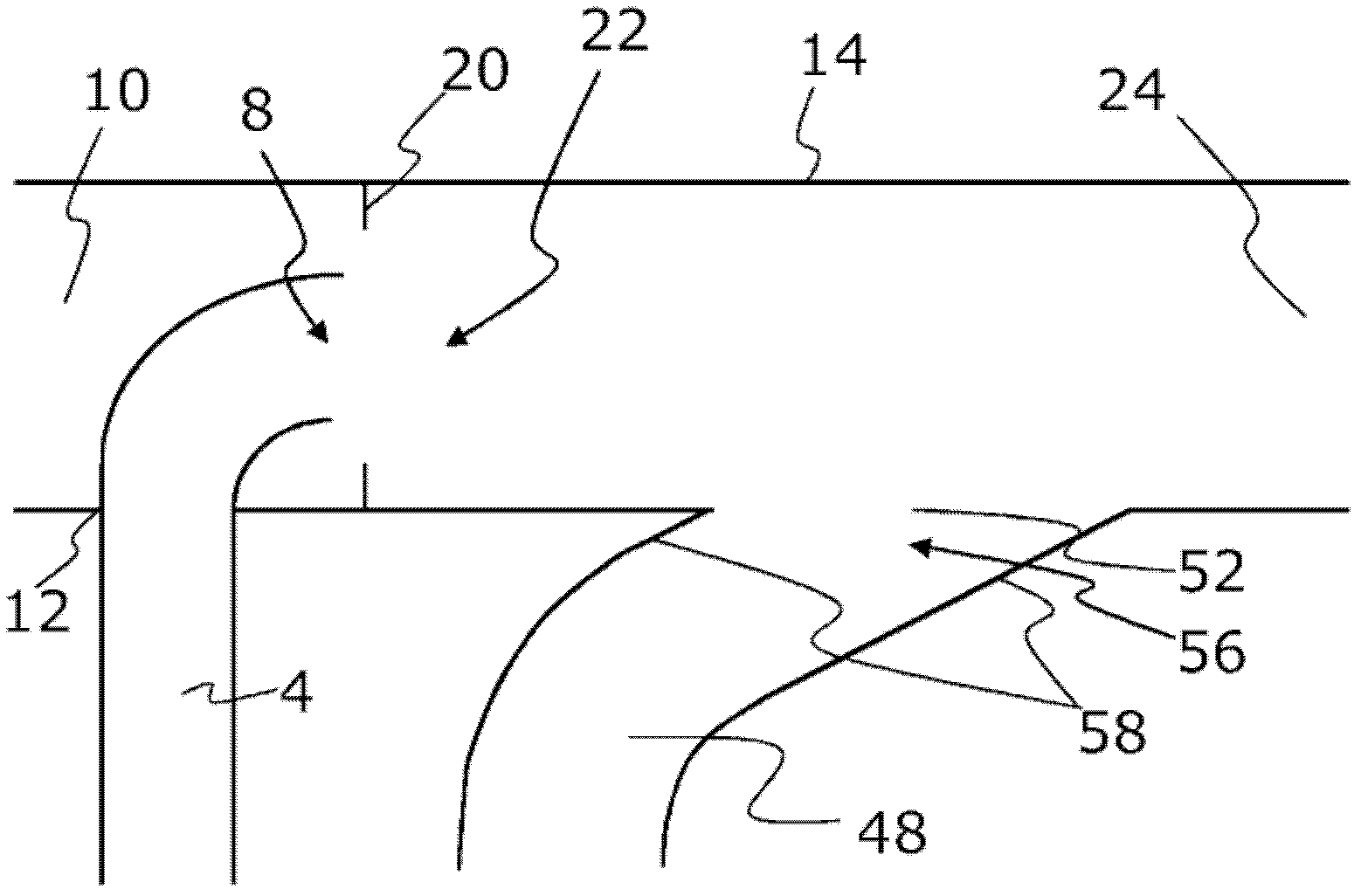
[0024] The exhaust gas channel 4 has a pipe end 8 which opens concentrically into the interior of the first air channel 10 . For this purpose, the first air channel has in its boundary wall 14 a hole 12 through which the exhaust gas channel 4 projects vertically into the air channel 10 . In order to open concentrically into the air duct 10 , the exhaust gas duct 4 has a 90° bend.

[0025] At the beginning of the air channel 10 there is a first air filter 16 , usually consisting of three filters, through which air can be drawn into the air channel 10 . The first regulating valve 18 ...


PUM

PropertyMeasurementUnit
Angleaaaaaaaaaa

Abstract

Systems for taking exhaust gas samples are known. Use is normally made of CVS systems in which an exhaust gas channel (4) is fluidically connected to an exhaust gas source (6) via an exhaust gas inlet (2) and an air channel (10), into which ambient air is sucked via an air filter (16), opens in a first mixing zone (22) which merges into a dilution tunnel (24) from which the samples are taken. The invention now proposes that the system have a second exhaust gas channel (38) which is fluidically connected to a second exhaust gas source (36) via a second exhaust gas inlet (34) and has a second mixing zone (46), wherein the diluted exhaust gas/air mass flows flow either from the first exhaust gas source (6) or from the second exhaust gas source (36) into the one dilution tunnel (23) and to the sampling probe (26). A particularly advantageous embodiment is described in this respect. The system is suitable for the connection of diesel and spark ignition engines, the exhaust gas of which can thereby be removed and analysed for the first time via only one sampling point and using only one dilution tunnel and one pump in a common system.

Description

technical field [0001] The present invention relates to a device for extracting a sample of exhaust gas from an internal combustion engine, the device having: a first exhaust gas channel in fluid communication with a first exhaust gas source via a first exhaust gas inlet; a first air channel capable of Ambient air is sucked into the first air channel via a first air filter; a first mixing zone, in which the first exhaust air channel opens into the first air channel; a dilution channel, exhaust air - Air mixture flows through said dilution channel; at least one sampling probe; pumps for conveying air and exhaust gas; and means for regulating and measuring the mass flow. Background technique [0002] Various national regulations exist according to which motor vehicle engines must not exceed certain emission limit values, for example ECE Directive 83 for Europe or Chapter 40 of the Code of Federal Regulations (40 CFR) for the United States. In addition to the emission limit va...

Claims


Application Information

Patent Timeline
IPC IPC(8): G01M15/10
CPCG01M15/02G01M15/102G01N1/2252G01N2001/2264
Inventor A.迪考
Owner AVL EMISSION TEST SYST GMBH
Why Eureka
Try Eureka