Aeration device with low gas pressure loss

An aeration device, gas pressure technology, applied in the direction of sustainable biological treatment, water/sludge/sewage treatment, biological water/sewage treatment, etc., can solve problems such as difficult efficacy, easy blockage of jet holes, etc., and reach the scope of application Wide, long service life, stable work effect

Inactive Publication Date: 2012-03-21
王杰
View PDF4 Cites 5 Cited by
  • Summary
  • Abstract
  • Description
  • Claims
  • Application Information

AI Technical Summary

Problems solved by technology

However, when using the intermittent aeration method, that is, aerating in the same biological reaction tank for several hours and then stopping the aeration for several hours, and then repeating the aeration and then stopping the sewage treatment, the air injection of the ordinary aeration device Pores are more prone to clogging, making it harder to function properly

Method used


Image

  • Aeration device with low gas pressure loss
  • Aeration device with low gas pressure loss
  • Aeration device with low gas pressure loss

Examples


Embodiment Construction

[0018] The preferred embodiments of the present invention will be described below in conjunction with the accompanying drawings. It should be understood that the preferred embodiments described here are only used to illustrate and explain the present invention, and are not intended to limit the present invention.

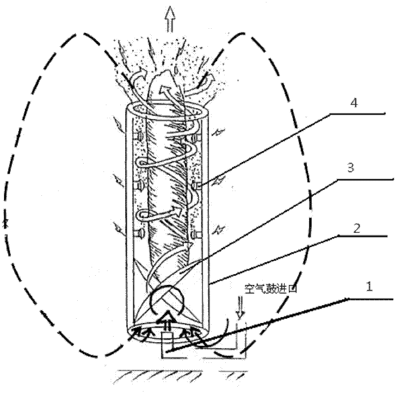
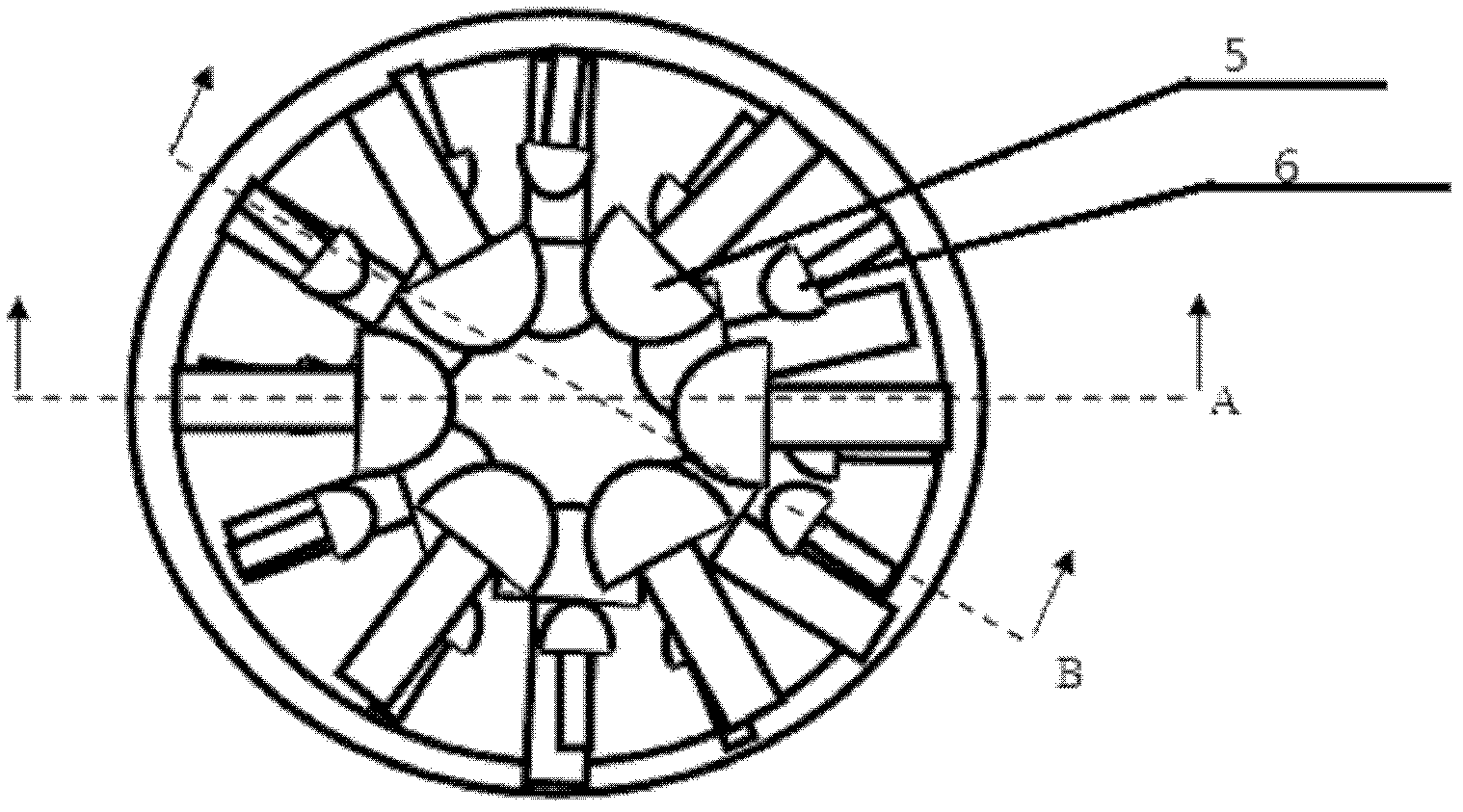
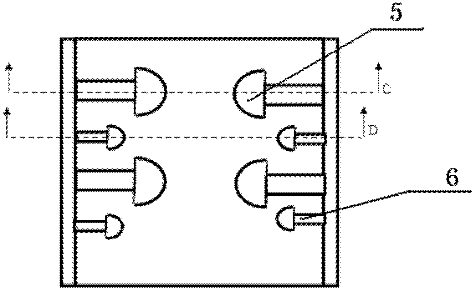
[0019] Such as figure 1 , figure 2 , image 3 , Figure 4 , Figure 5 , Figure 6 As shown, it includes an air supply pipe 1 and a gas-liquid mixing pipe 2. Below the gas-liquid mixing pipe 2, the air outlet of the air supply pipe 1 is inserted from the bottom of the gas-liquid mixing pipe 2. The diameter of the gas-liquid mixing pipe 2 is larger than that of the air supply pipe. 1, the gas-liquid mixing tube 2 is a straight tube, and the air supply tube 1 is a curved tube with two corners or other shapes such as arc-shaped tubes, and the gas is sent straight from the lower part of the gas-liquid mixing tube 2 into the gas-liquid mixing tube 2 within. The gas...


PUM


Abstract

The invention discloses an aeration device with low gas pressure loss, which comprises a gas-feeding pipe and a gas-liquid mixing pipe; the gas-feeding pipe is inserted into the lower end part of the gas-liquid mixing pipe; a guiding resistance plate and a rivet cap-shaped protrusion are disposed on the inner wall of the gas-liquid mixing pipe; the rivet cap-shaped protrusion are disposed above the guiding resistance plate. The number of the guiding resistance plate is two, and the guiding resistance plates are intercrossingly distributed. The guiding resistance plate is an crescent arc. The rivet cap-shaped protrusion comprises two types, a big rivet cap-shaped protrusion and a small rivet cap-shaped protrusion. The invention has a long service life, and is not easy to obstruct, and the aeration area is larger than that of a common aeration device by 5-7 times.

Description

[0001] technical field [0002] The invention relates to the field of sewage treatment equipment, in particular to a sewage treatment reaction tank device. Background technique [0003] In the biological reaction tank of sewage treatment, the bottom of the tank usually uses a diffuser or aeration device. Ordinary aeration devices are mostly disc-shaped aeration heads, with holes on the upper part for gas injection, or aeration tubes with holes in the tube wall for gas injection. After the gas is ejected, it uses its buoyancy to naturally rise to the liquid surface. In order to improve the utilization rate of oxygen, that is, the ratio of the oxygen in the air sent to the aeration tank to be digested by the microorganisms in the aeration tank, the pores are generally small, so that smaller bubbles can be ejected to increase the residence time in the liquid. , which also leads to a large pressure loss of the gas, and the accumulation of sludge is inevitable in the lower part...

Claims


Application Information

Patent Timeline
Patent Type & Authority Applications(China)
IPC IPC(8): C02F3/12
CPCY02W10/10
Inventor 王杰
Owner 王杰
Why Eureka
Try Eureka