
Natural gas pressure difference generating system self-adaptive to back-end load change

A power generation system and load change technology, applied in engine components, machines/engines, and mechanisms that generate mechanical power, etc., can solve problems such as large fluctuations in natural gas flow, improve power generation efficiency, solve inconvenience in transportation and use, and increase system reliability. sexual effect

Inactive Publication Date: 2012-03-21
CHONGQING GIENT ENERGY SAVING TECH
View PDF7 Cites 6 Cited by
  • Summary
  • Abstract
  • Description
  • Claims
  • Application Information

AI Technical Summary

Problems solved by technology

[0008] The purpose of the present invention is to address the deficiencies in the prior art, and propose a natural gas differential pressure power generation system that adapts to changes in back-end loads, uses natural gas pressure differentials to generate power, and solves the problem of large load fluctuations in natural gas flow in pressure regulating stations. Significantly improve the reliability, stability and adaptability of the entire power generation system

Method used


Image

  • Natural gas pressure difference generating system self-adaptive to back-end load change
  • Natural gas pressure difference generating system self-adaptive to back-end load change
  • Natural gas pressure difference generating system self-adaptive to back-end load change

Examples


Embodiment Construction

[0022] The natural gas differential pressure power generation system adaptive to back-end load changes provided by the present invention will be described in detail below with reference to the drawings and specific embodiments.

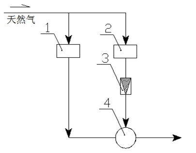
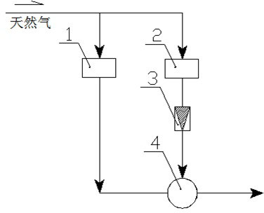
[0023] Such as figure 1 , figure 2 As shown, the natural gas differential pressure power generation system is composed of a natural gas load automatic bypass step-down voltage stabilization system 1, a natural gas differential pressure power generation system 2, a pressure stabilizing valve 3, and a pressure stabilizing tank 4.

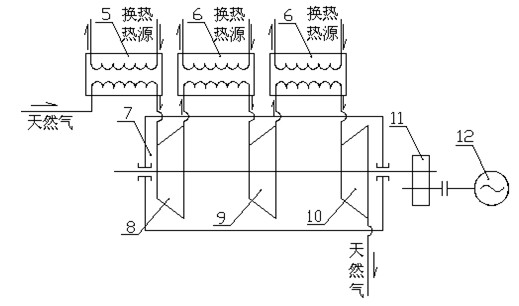
[0024] Such as figure 2 As shown, the natural gas differential pressure power generation system 2 mainly includes a front-end preheater 5 , an intermediate reheater 6 , a multistage centripetal turbo expander unit 7 , a speed reducer 11 and a generator set 12 . The inlet end of the preheater 5 is connected to natural gas, and the gas outlet end is connected to the inlet end of the single-stage or multi-stage centripetal t...


PUM


Abstract

The invention discloses a natural gas pressure difference generating system self-adaptive to the back-end load change, and the natural gas pressure difference generating system self-adaptive to the back-end load change comprises the natural gas pressure difference generating system and a load automatic bypass pressure decreasing and pressure stabilizing system, wherein the natural gas pressure difference generating system mainly comprises: a single-stage or a multistage centripetal turbine expansion machine set, the front-end preheater of the expansion machine set, the interstage middle reheater of the expansion machine set, a speed reducer, a generator set and the like. The system to which the invention relates is mainly characterized in that one set of the load automatic bypass pressure decreasing and pressure stabilizing system is arranged near the natural gas pressure difference generating system and synchronously runs together with the natural gas pressure difference generating system, and the amount of natural gas entering a back-end pipe network is regulated by utilizing the load automatic bypass pressure decreasing and pressure stabilizing system, so as to solve the problem that a natural gas expansion machine set is difficult to meet the load change, and greatly promote the stability and the adaptability of the whole natural gas pressure difference generating system. Moreover, a pressure stabilizing valve can be added at the back end of the natural gas pressure difference generating system, and a natural gas pressure stabilizing tank can be added at the tail end of the system, so that the natural gas pressure of the back-end pipe network can be further stabilized, the stability of the natural gas pressure difference generating system is promoted again, and the adaptability of the natural gas pressure difference generating system is increased.

Description

technical field [0001] The invention relates to the technical field of waste heat and pressure power generation. Background technique [0002] Natural gas has a relatively high pressure after being extracted from the ground, usually between several MPa and tens of MPa. The long-distance transportation of natural gas is also carried by high-pressure pipelines above 4MPa. When it enters the urban pipeline network or the pipeline network of large-scale gas-consuming enterprises, the pressure of natural gas is usually reduced to medium pressure (about 0.4MPa) through a pressure regulating station. The decompression process generally adopts throttling and decompression. At present, this part of the pressure difference energy has not been well utilized. [0003] Using the pressure difference of the natural gas pressure regulating station to generate power is a topic that has been discussed in my country's gas industry for many years but has not been resolved. The difficulty mainl...

Claims


Application Information

Patent Timeline
Patent Type & Authority Applications(China)
IPC IPC(8): F01D15/10F01D25/10F03G7/00
Inventor 赵志立赵征鹏彭俊
Owner CHONGQING GIENT ENERGY SAVING TECH
Learn More