Vertical smoke tube exhaust-heat boiler

A waste heat boiler and smoke tube technology, applied in the field of waste heat boilers, can solve the problems of corrosion on the heating surface, difficulty in cleaning ash, burst tubes, etc., and achieve the effect of high-efficiency heat transfer

Inactive Publication Date: 2012-03-21
DALIAN EAST NEW ENERGY DEV
View PDF8 Cites 2 Cited by
  • Summary
  • Abstract
  • Description
  • Claims
  • Application Information

AI Technical Summary

Problems solved by technology

After the heating area of ​​the boiler is ash, in addition to reducing the thermal efficiency of the boiler, it will also cause corrosion of the heating surface. In order to ensure the cleanliness of the heating surface, steam, pulse and vibration cleaning methods are often used in the design. While using these cleaning methods, It not only increases energy consumption, but also causes damage to the equipment, such as cracks at the pipe end when using rapping to clean the dust, and pipe bursting on the heating surface when steam soot blowing, etc.
Especially when pulse soot blowing and steam soot blowing are used, the combination of corrosive components in the flue gas and water vapor is intensified, the dew point of the flue gas is increased, and the heating surface of the boiler begins to corrode at a higher temperature. Accumulation, combined with the action of water vapor, makes cleaning more difficult to remove

Method used


Image

  • Vertical smoke tube exhaust-heat boiler
  • Vertical smoke tube exhaust-heat boiler
  • Vertical smoke tube exhaust-heat boiler

Examples


Embodiment Construction

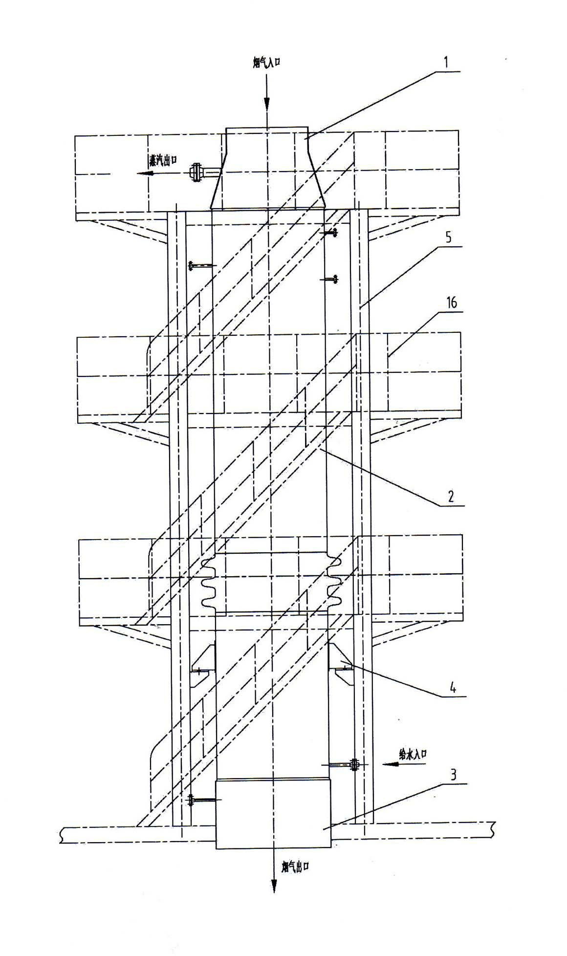
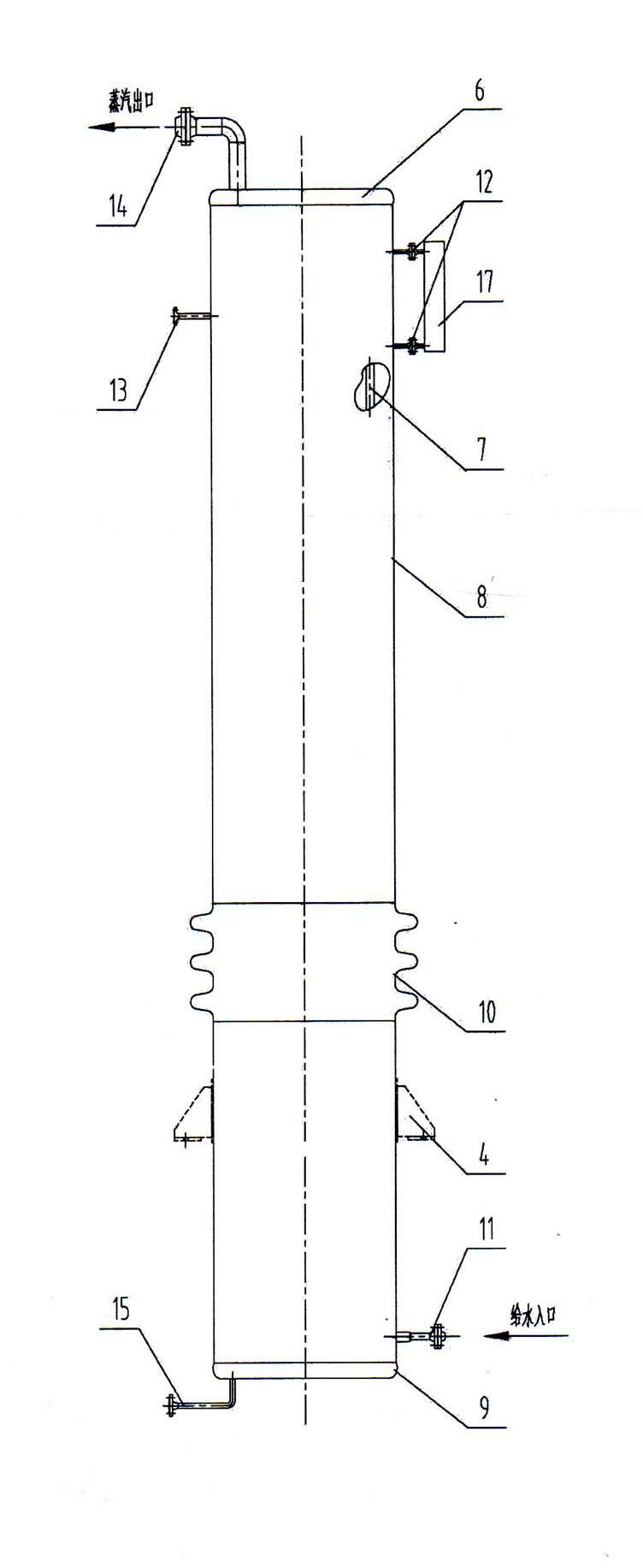
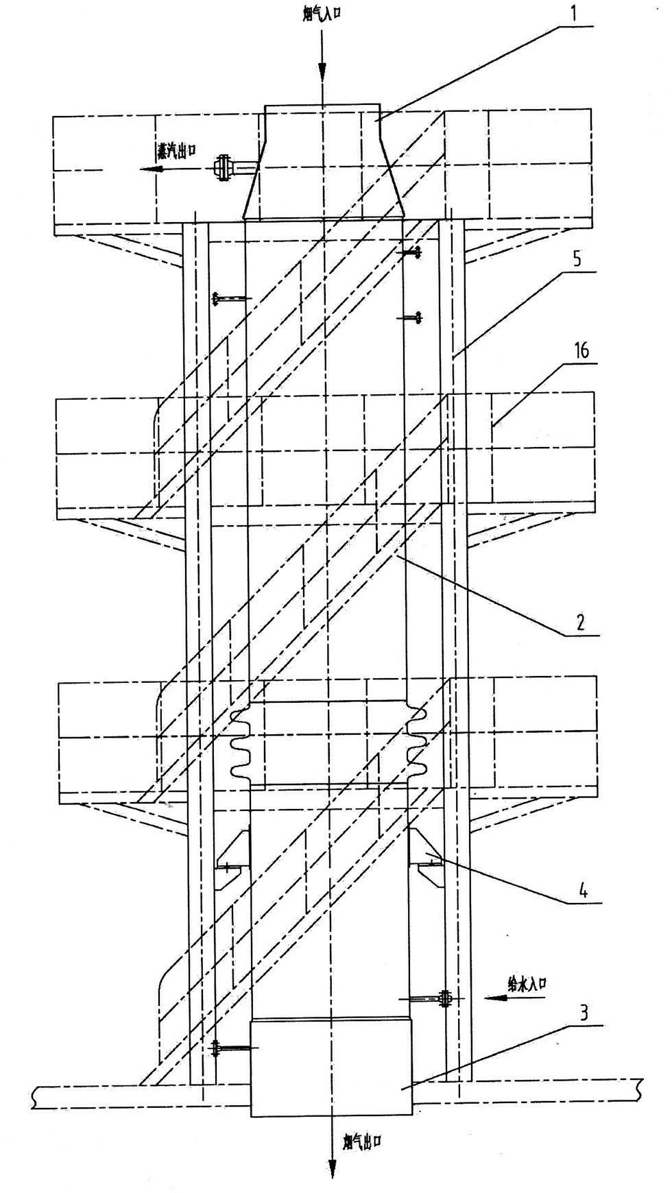
[0017] exist figure 1 and figure 2 In the schematic diagram of the vertical smoke tube waste heat boiler shown, the drum 2 is a vertical cylinder with an upper tube plate 6 at its upper end opening and a lower tube plate 9 at its lower end opening. Several vertical smoke tubes 7. The two ends are respectively fixed on the corresponding through holes of the upper tube plate 6 and the lower tube plate 7 to form a smoke tube bundle. A flue gas inlet smoke box 1 is provided at the upper end of the drum 2, and a smoke outlet smoke box 3 is provided at the lower end of the drum 2, and the three are connected together. The lower part of the outer wall of the above-mentioned drum 2 is provided with a feedwater inlet pipe 11 communicating with the cavity thereof, and the upper part of the upper tube plate 6 is provided with a steam outlet pipe 14 communicating with the cavity of the drum 2, which passes through the steam outlet of the flue gas inlet smoke box 1 Tube 14 may be connec...


PUM


Abstract

The invention relates to a vertical smoke tube exhaust-heat boiler. In the vertical smoke tube exhaust-heat boiler, a boiler cylinder is a vertical cylinder body; pipe plates are arranged at openings at upper and lower ends of the boiler cylinder; two ends of a vertical smoke tube are fixedly arranged on through holes corresponding to the upper pipe plate and the lower pipe plate to form a smoke tube bundle; a flue gas inlet smoke box is arranged at the upper end of the boiler cylinder, a flue gas outlet smoke box is arranged at the lower end of the boiler cylinder, and the flue gas inlet smoke box, the flue gas outlet smoke box and the boiler cylinder are connected together; a water supply hole communicated with a cavity of the boiler cylinder is formed on the lower part of the wall of the boiler cylinder; a steam outlet communicated with the cavity of the boiler cylinder is formed on the upper part of the upper pipe plate, and a connection pipe passing through the flue gas inlet smoke box is arranged on the steam outlet; a support is arranged on the outer wall of the boiler cylinder, so that the boiler cylinder is fixed on a steel frame by the support; and the steel frame corresponds to the boiler cylinder and is fixed on a foundation. The vertical smoke tube exhaust-heat boiler has the characteristics of efficient heat transfer, automatic ash removal, modularization and low exhaust gas resistance.

Description

technical field [0001] The invention relates to a waste heat boiler, in particular to a waste heat recovery boiler at the tail end of a cement kiln. Background technique [0002] In the existing cement kiln tail waste heat utilization system, water tube waste heat boilers are mostly used. Due to the low temperature of the exhaust gas at the tail of the cement kiln, when the heating surface is designed with a bare tube, the steel consumption is large; in order to reduce the steel consumption of the heating surface and increase the heating area, the recent boiler design often uses an extended heating surface structure, such as spiral fins Sheet or H-type finned tube structure. Due to the large amount of dust in the flue gas at the kiln tail, the ensuing problem is the ash on the heating area, which leads to low efficiency of this type of boiler in actual operation and high exhaust gas temperature. When the ash accumulation is serious, the boiler may even be blocked, resulting...

Claims


Application Information

Patent Timeline
Patent Type & Authority Applications(China)
IPC IPC(8): F22B1/18F22B37/06
Inventor 唐金泉金万金庄宇刚孙明朗
Owner DALIAN EAST NEW ENERGY DEV
Why Eureka
Try Eureka