Digital controllable annular voltage-controlled oscillator circuit

A voltage-controlled oscillator and ring technology, applied in the field of microelectronics, can solve the problems of poor phase noise and low quality factor of the loop, and achieve the effects of phase noise optimization, digital process compatibility, and reduced impact

Inactive Publication Date: 2012-03-21
HANGZHOU DIANZI UNIV
View PDF9 Cites 8 Cited by
  • Summary
  • Abstract
  • Description
  • Claims
  • Application Information

AI Technical Summary

Problems solved by technology

The ring oscillator has the advantages of good process compatibility, wide tuning range and

Method used


Image

  • Digital controllable annular voltage-controlled oscillator circuit
  • Digital controllable annular voltage-controlled oscillator circuit
  • Digital controllable annular voltage-controlled oscillator circuit

Examples


Embodiment Construction

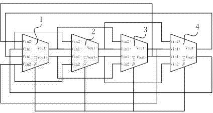
[0017] Such as figure 1 As shown, the digitally controllable ring voltage controlled oscillator circuit includes four stages of delay units.

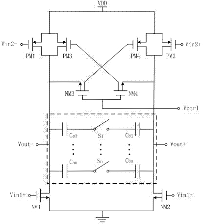
[0018] Such as figure 2 As shown, the delay unit includes four NMOS transistors, four PMOS transistors and a switched capacitor array.

[0019] The switched capacitor array (the dotted box in the figure) includes n switch units connected in parallel, and each switch unit includes a switch S 1 ┄S n and two switched capacitors, the switched capacitor consists of the pre-switched capacitor C a1 ┄C an and post switch capacitor C b1 ┄C bn , the front switching capacitor C in each switching cell a1 ┄C an One end of the switch is connected to one end of the switch, after the switch capacitor C b1 ┄C bn One end of the switch is connected to the other end of the switch; the front switching capacitor C in each switching unit a1 ┄C an The other end is connected to the drain of the first NMOS transistor NM1, the source of the third NMO...


PUM


Abstract

The invention relates to a digital controllable annular voltage-controlled oscillator circuit. The current product has low quality factor and poor phase noise. The circuit comprises a multistage delay unit, and each stage includes four NMOS (N-channel Metal Oxide Semiconductor) tubes, four PMOS (P-channel Metal Oxide Semiconductor) tubes and a switch capacitor array; a plurality of switch units are connected in parallel to form a switch capacitor array, and the switch capacitor is a three-dimensional interdigital capacitor; the first same-phase input end of the middle stage delay unit is connected with the reverse phase output end of the previous stage and the second same-phase input end of the next stage, the first reverse phase input end of the middle stage delay unit is connected with the same-phase output end of the previous stage and the second reverse phase input end of the next stage, the second same-phase input end of the middle stage delay unit is connected with the first same-phase input end of the previous stage, the second reverse phase input end of the middle stage delay unit is connected with the first reverse phase input end of the previous stage, the reverse phase output end of the middle stage delay unit is connected with the first same-phase input end of the next stage, the same-phase output end of the middle stage delay unit is connected with the first reverse phase input end of the next stage, and the first stage delay unit is reversely connected with the last stage delay unit. The digital controllable annular voltage-controlled oscillator circuit increases the oscillating frequency, reduces the phase noise and has the advantages of high capacitor density and compatibility with digital technology.

Description

technical field [0001] The invention belongs to the technical field of microelectronics and relates to a digital controllable ring voltage-controlled oscillator circuit. Background technique [0002] With the rapid development of integrated circuit technology, the operating speed of microprocessors is getting higher and higher, so corresponding circuits are required to generate high-performance clock signals. Usually an active or passive crystal oscillator is used to generate a stable clock signal, but the frequency of the output signal is low. Therefore, the frequency multiplication effect of the phase-locked loop is usually used to generate a high-frequency clock signal. [0003] Commonly used phase-locked loops for generating clocks include analog phase-locked loops and digital phase-locked loops. Digital phase-locked loops are mainly limited by the working speed; at the same time, they also have disadvantages in terms of chip power consumption and the number of pins. ...

Claims


Application Information

Patent Timeline
IPC IPC(8): H03L7/099
Inventor 高海军孙玲玲
Owner HANGZHOU DIANZI UNIV
Why Eureka
Try Eureka