Digital pulse width modulator based on digital delayed-locked loop (DLL)

A technology of digital pulse width modulation and delay phase-locked loop, which is applied in the direction of automatic power control and electrical components, can solve the problems of large area and achieve the effect of simple circuit structure, cost saving and area reduction

Inactive Publication Date: 2012-03-28
SOUTHEAST UNIV
View PDF5 Cites 19 Cited by
  • Summary
  • Abstract
  • Description
  • Claims
  • Application Information

AI Technical Summary

Problems solved by technology

[0005] The invention provides a digital pulse width modulator based on a digital delay phase-locked loop. On the basis of maintaining the advantages of no frequency drift and good linearity in the original digital DLL DPWM scheme, it adopts a simplified programmable delay unit structure , which solves the problem that the required area is too large

Method used


Image

  • Digital pulse width modulator based on digital delayed-locked loop (DLL)
  • Digital pulse width modulator based on digital delayed-locked loop (DLL)
  • Digital pulse width modulator based on digital delayed-locked loop (DLL)

Examples


Embodiment Construction

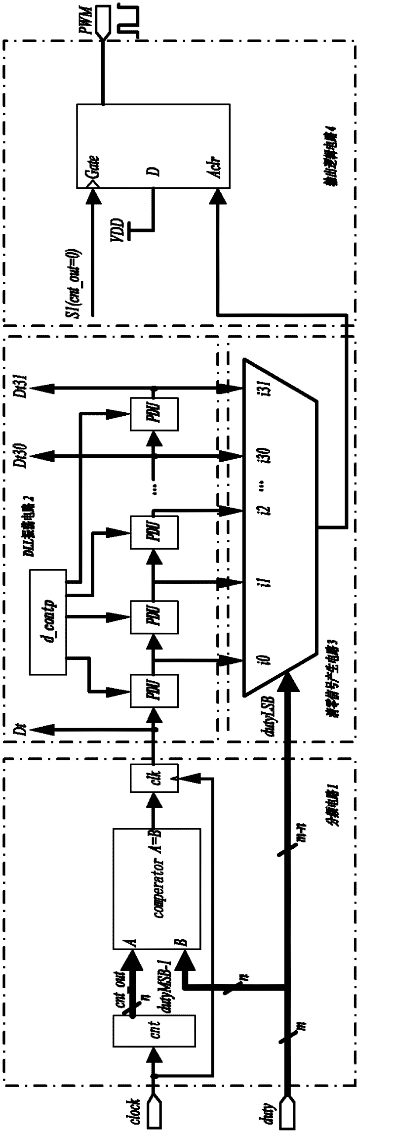
[0026] see Figure 4 , the present invention is based on the digital pulse width modulator of digital delay locked loop, comprises frequency division circuit 1, DLL oscillation ring circuit 2, reset signal generation circuit 3 and PWM output logic circuit 4, and prior art also includes these 4 parts.

[0027] The frequency division circuit 1 includes a counter 11 and a comparator 12, the clock signal input end of the counter 11 is connected with the system clock, the reset signal input end of the counter 11 is connected with the system reset signal, and the output of the counter 11 is connected with an input end of the comparator 12 , the other input terminal of the comparator 12 is grounded;

[0028] Clearing signal generation circuit 3 comprises comparator 31, selector 32 and a two-input AND gate 33, and an input end of comparator 31 is connected the output of counter 11 in frequency division circuit 1, and the other input end of comparator 31 is connected input The high nM...


PUM


Abstract

The invention discloses a digital pulse width modulator based on a digital delayed-locked loop (DLL). The digital pulse width modulator comprises: a frequency division circuit, a DLL oscillation loop circuit, a reset signal generation circuit and a PWM output logic circuit. By using inputting a high frequency clock signal fs, the DLL oscillation loop triggers a oscillation loop to perform concussion outputting a 2 channel signal and then the signal is sent to the reset signal generation circuit. The reset signal generation circuit combines the input fs and a duty ratio command signal of mbits so as to generate a pulse signal PWM_clr. Under an effect of post-stage PWM output logic circuit, the PWM signal is generated so as to be taken as the output of the system. The DLL oscillation loop circuit uses a programmable delay unit (PDU) to real-timely track the input signal so that the effect of outputting a good pulse width modulation wave under different process corners and differentworking environments can be achieved. By using the digital pulse width modulator of the invention, areas needed by a chip can be minimized to a larger degree and costs of chip development can be saved.

Description

technical field [0001] The invention relates to a digital pulse width modulation circuit (DPWM) of a digitally controlled switching power supply, in particular to a digital pulse width modulator based on a digital delay-locked loop used in a digitally controlled switching power supply circuit whose output voltage can be adjusted in real time. Electronic technology field of integrated circuit design. Background technique [0002] The switching power supply with digital feedback control can significantly improve the performance of the system. The digital control method is flexible and changeable, and complex control algorithms can be realized, and the sensitivity to changes in external conditions is low. Therefore, more and more digital control switching power supplies are applied to SoC systems to provide high-quality power supply voltages, which in turn put forward higher requirements for power supplies. [0003] The smaller and smaller power supply ripple means that the qu...

Claims


Application Information

Patent Timeline
Patent Type & Authority Applications(China)
IPC IPC(8): H03L7/18H03L7/099
Inventor 徐申王青梁雷孙伟锋陆生礼时龙兴
Owner SOUTHEAST UNIV
Why Eureka
Try Eureka