
Composite bit formed by rotary cut bit and roller bit

A technology of roller cone bit and composite bit, which is applied to drill bits, drilling equipment, earth-moving drilling, etc., can solve the problems of low rock-breaking efficiency, tooth loss, inability to effectively improve bearing size, etc., and achieve the effect of improving rock-breaking efficiency.

Active Publication Date: 2012-04-04
SICHUAN DEEP & FAST OIL DRILLING TOOLS CO LTD
View PDF7 Cites 6 Cited by
  • Summary
  • Abstract
  • Description
  • Claims
  • Application Information

AI Technical Summary

Problems solved by technology

Since the compressive strength of the rock is much greater than the shear and tensile strength, and the three-cone bit uses the impact of the teeth on the rock to break the rock, the energy utilization rate is not high
Especially in the case of high drilling pressure such as deep well drilling, due to the action of high-density drilling fluid, the cuttings holding effect at the bottom of the well is obvious, and it is difficult for the drill bit teeth to impact the broken rock, so the rock breaking efficiency is relatively low
[0004] The bearing life of the tri-cone bit is one of the main factors restricting the service life of the bit. The bearing bears the load caused by the drilling pressure. In addition, the tri-cone bit breaks the rock in the form of impact. The impact load on the bearing is large, and the load amplitude is high. In addition, The speed-up effect of the tri-cone bit: the body speed ratio of the tri-cone bit (the ratio of the rotational speed of the cone to the rotational speed of the bit during drilling) is greater than 1, that is, the rotational speed of the cone is greater than the speed of penetration of the bit when the bit is drilling, so the rotational speed of the bearing is relatively low. faster, resulting in shorter bearing life for tricone bits
The single cone bit is characterized by low cone speed, large bearing size, and longer service life than the three-cone bit. However, the single-cone bit has unavoidable shortcomings: the full-hole structure of the single-cone bit determines its rock-breaking process. Prone to repeated crushing and difficult chip removal
[0008] (1) High requirements on the bottom of the well: If there are foreign objects at the bottom of the well, it will cause chipping or thermal friction of the PDC bit, the temperature will rise and the carcass will be blackened, and even the brazing layer will be melted, resulting in tooth loss and affecting the ROP. Accelerated bit failure
[0009] (2) Serious consequences of PDC tooth failure: Compared with the roller cone bit, the failure of individual teeth of the PDC bit (tooth loss, tooth collapse, etc.) will seriously increase the load of nearby PDC teeth, accelerate its wear rate, and aggravate the failure of the drill bit
[0010] (3) The rock-breaking efficiency of the core is not high: the wear speed of the PDC teeth on different radial regions of the PDC bit is significantly different, and the outer shoulder cuts a large proportion of rocks, and the wear speed is fast
[0012] (1) The efficiency of center rock breaking is not high: since the composite drill bit is composed of roller cone bits, its rock breaking form is still impact crushing, and the energy utilization rate is not high
Like the roller cone bit, in the case of high bit pressure, due to the effect of high-density drilling fluid, the cuttings holding effect at the bottom of the well is obvious, and the bit teeth are difficult to impact and break rock, and the rock breaking efficiency is relatively low, especially in the borehole. In the center, the situation is more serious
[0013] (2) Severe wear and tear on the peripheral bit of the wellbore: near the periphery of the wellbore of this type of compound drill bit, the cone size of the roller cone bit is relatively small, but the high speed of the drilling process will accelerate the wear and failure of the bit, and at the same time cause the bit to appear molar back Phenomenon
[0014] (3) The service life of the central and peripheral cones is not equal, and the service life of the composite drill bit is not high: based on the rock-breaking mechanism and structural composition of this type of composite drill bit, the rock-breaking efficiency of the center is not high, while the structure size of the cones on the periphery of the borehole is small and the speed is low. High and severe wear, resulting in differences in the life of the roller cone bits in the center of the wellbore and the periphery of the wellbore, making it difficult to achieve overall optimization and life improvement of the composite drill bit
The rock breaking at the center of the composite drill bit is completed by the blade, which still cannot change the low efficiency of rock breaking at the center of the PDC bit
At the same time, the roller cone drill in the composite drill bit still cuts the periphery of the borehole with a large circle, and the small ring gear cuts the center of the borehole, which cannot effectively improve the bearing size and the life of the drill bit.

Method used

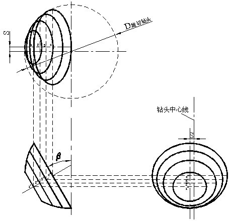

Image

  • Composite bit formed by rotary cut bit and roller bit
  • Composite bit formed by rotary cut bit and roller bit
  • Composite bit formed by rotary cut bit and roller bit

Examples


Embodiment 1

[0061] When the rotary cutting drill bit of the present invention , ,diameter , the drilling speed is , the materials used in the experiment were Hongya stone: , green sandstone: During the experiment, rock cuttings were collected, the difficulty of rock breaking and vibration were analyzed, the wear marks and directions of cutting teeth were checked, and the wheel body speed ratio of the cone and the drill bit was calculated.

[0062] The results of the examples and the theoretical calculations also show that: under the corresponding parameter conditions in Example 1, the wheel body speed ratio is less than 1, and in this example it is less than 0.55; the harder the lithology, the higher the cone speed, and the higher the wheel body speed ratio.

Embodiment 2

[0064] when gear 2 , ,diameter , the drilling speed is , the materials used in the experiment are Hongya stone: , green sandstone: During the experiment, rock cuttings were collected, the difficulty of rock breaking and vibration were analyzed, the wear marks and directions of cutting teeth were checked, and the wheel body speed ratio of the cone and the drill bit was calculated.

[0065] Embodiment result and theoretical calculation show simultaneously: corresponding , the harder the lithology, the lower the speed of the cone, and the speed ratio of the wheel body is smaller than the value corresponding to Example 1.

[0066] Comprehensive comparative analysis of the above implementation results can be obtained: the cutting teeth of the rotary cutting drill bit in the composite drill bit of the present invention break rocks in a rotary cutting mode, have better dynamic performance, uniform wear, improved bearing working conditions, long service life of the drill b...


PUM


Abstract

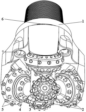
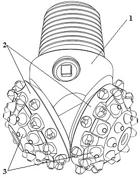
The invention discloses a composite bit formed by a rotary cut bit and a roller bit, comprising a main body (1), a rotary cut bit roller (2), a rotary cut bit cutting tooth (3), a roller bit roller (4), a roller bit cutting tooth (5), an oil storage bag (6) and a spray nozzle (7). The main body (1) of the bit comprises a roller axle journal, a straightening block, a high-pressure slurry channel and a connection thread. The composite bit formed by rotary cut bit and roller bit has the characteristics that: a composite bit cutting unit comprises the rotary cut bit and a roller bit cutting unit. When in a drilling process, the drilling of the central part of a borehole is completed by the rotary cut bit, and the drilling of the periphery of the borehole is completed by the roller bit. The rotary cut bit in the composite bit impacts, presses and cuts the rock in a rotary cutting way, has high central rock breaking efficiency and mechanical drilling speed, has better mechanical properties, wears uniformly, simultaneously improves a bearing structure of the bit, ensures to improve the rock breaking efficiency and prolong the service life of the bit, and has good diameter keeping effect. Different composite structures in the composite bit can achieve the effects of high rock breaking performance and high mechanical drilling speed.

Description

technical field [0001] The invention belongs to the field of technical equipment such as oil and gas drilling engineering, mining, geological drilling, construction engineering, tunnel engineering, shield tunneling and non-excavation, and relates to a composite drill bit formed by a rotary cutting bit and a roller cone bit. Background technique [0002] The drill bit is a tool that directly contacts the rock during the drilling process and breaks the rock through cutting and punching. The drill bits widely used in modern drilling engineering mainly include roller cone bits and PDC bits (Polycrystalline Diamond Compact Bits). Today, both the roller cone bit and the PDC bit have been developed to a fairly high level, but there are still some insurmountable problems. One is fear of reaming and reaming, which will damage the roller cone bit of the sealed bearing, especially the PDC bit; the other is that the movement of the center rock at the bottom of the well is small, the fu...

Claims


Application Information

Patent Timeline
IPC IPC(8): E21B10/00E21B10/43E21B10/16E21B10/46
Inventor 李舒田家林曾德发杨琳
Owner SICHUAN DEEP & FAST OIL DRILLING TOOLS CO LTD
Learn More