
Composite equipment for flue gas waste heat recovery and dust cleaning

A flue gas waste heat and composite technology, which is applied in the direction of combined devices, chemical instruments and methods, and the separation of dispersed particles, can solve the problems of large space occupation, large flow resistance, and many equipment, so as to improve the purification level, prevent corrosion, The effect of increasing the surface area

Active Publication Date: 2012-04-11
BEIJING UNIVERSITY OF CIVIL ENGINEERING AND ARCHITECTURE +1
View PDF3 Cites 17 Cited by
  • Summary
  • Abstract
  • Description
  • Claims
  • Application Information

AI Technical Summary

Problems solved by technology

[0006] The purpose of the present invention is to provide a flue gas waste heat recovery and dust removal and purification composite device, in order to solve the problem of multiple equipment, large space occupation, high investment, Problems such as large flow resistance and high energy consumption can achieve the purpose of using low-carbon energy-saving and emission-reduction technologies to minimize product costs, reduce energy consumption, deeply recover flue gas waste heat and dust removal and purification, thereby improving the cost performance of this type of product

Method used


Image

  • Composite equipment for flue gas waste heat recovery and dust cleaning
  • Composite equipment for flue gas waste heat recovery and dust cleaning
  • Composite equipment for flue gas waste heat recovery and dust cleaning

Examples


Embodiment Construction

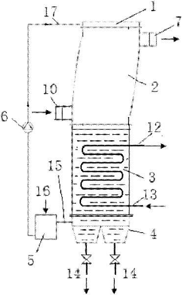
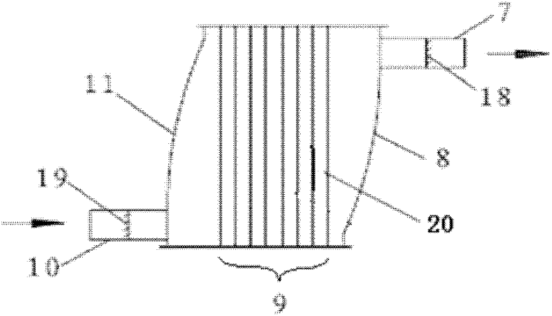
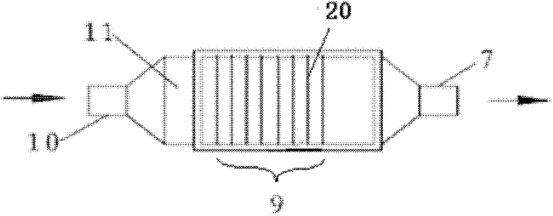
[0019] The structure, principle and working process of the present invention will be further described below in conjunction with the accompanying drawings.

[0020] figure 1 It is a schematic diagram of the overall structure and principle of a flue gas waste heat recovery and dust removal and purification composite equipment provided by the present invention. The equipment includes a heat exchange and absorption composite device 2, a partition heat exchanger 3, a sediment collection and sewage discharge device 4, and a solution pool 5 and liquid pump6. A liquid distributor 1 is arranged on the top of the heat exchange and absorption composite device 2, the partition heat exchange device 3 is located at the bottom of the heat exchange and absorption composite device, and the sediment collection and sewage discharge device 4 is located at the bottom of the partition heat exchange device; the solution pool 5 The inlet is connected to the sediment collection and sewage device thr...


PUM


Abstract

The invention relates to composite equipment for flue gas waste heat recovery and dust cleaning, belonging to the technical field of flue gas waste heat recovery and dust cleaning. The equipment comprises a heat exchange and absorption compound device, a recuperative heat exchanger, a precipitate collection and pollutant discharge device, a solution pool and a liquid pump, wherein a liquid distributor is arranged at the top of the heat exchange and absorption compound device, the recuperative heat exchanger is located at the lower part of the heat exchange and absorption compound device, and the precipitate collection and pollutant discharge device is arranged at the lower part of the heat exchange and absorption compound device; the heat exchange and absorption compound device comprises a flue gas inlet section, a flue gas inlet diversion section, a heat exchange and absorption section, a flue gas outlet liquid baffle diversion section and a flue gas inlet section, and a liquid mesh type liquid membrane distribution net is arranged inside the heat exchange and absorption section. Waste heat recovery and purification treatment are integrated, sensible heat and latent heat of exhausted flue can be recovered, the composite equipment also have the actions of corrosion prevention, dust removal, scale prevention, purification treatment and the like, flow resistance and energy consumption of fans and water pumps are also reduced, the cost of products is lowered, and the deep recovery of flue gas waste heat is achieved.

Description

technical field [0001] The invention relates to a composite equipment for recovery and utilization of waste heat of flue gas and dust removal and purification, in particular to a low-resistance type heat exchange and flue gas purification and dust removal integrated composite device utilizing the heat energy of condensation of flue gas, which belongs to the recovery and utilization of waste heat of flue gas and dust removal In the field of purification technology, it can be used for flue gas preheating, recycling and dust removal and purification of thermal power equipment such as ordinary coal-fired boilers, direct-fired engines, and cogeneration. Background technique [0002] Common boilers, direct-fired turbines, cogeneration and other thermal power equipment have high exhaust gas temperatures, most of which are above 120-200°C, resulting in energy waste and environmental pollution. The thermal efficiency is generally lower than 90%. Coal-fired boilers Generally less than...

Claims


Application Information

Patent Timeline
IPC IPC(8): B01D53/78B01D53/60B01D53/62B01D50/00
Inventor 王随林刘贵昌
Owner BEIJING UNIVERSITY OF CIVIL ENGINEERING AND ARCHITECTURE
Learn More