Resistance welding tube and manufacturing method and application thereof

A resistance welding and copper welding technology, applied in welding equipment, welding medium, welding/cutting medium/material, etc., can solve the problems of copper tube crystal grain size that cannot meet the requirements, high welding cost, high environmental pressure, etc., to achieve pressure resistance The effect of high strength, reduced welding cost, and reduced welding leak rate

Inactive Publication Date: 2012-04-11
DONGGUAN JINRUI HARDWARE PROD
View PDF6 Cites 19 Cited by
  • Summary
  • Abstract
  • Description
  • Claims
  • Application Information

AI Technical Summary

Problems solved by technology

The copper suction outer tube 3' and the iron shell 1 are welded by flame, and the auxiliary chemical preparations must be mixed, and silver solder is used, and the welding cost is very expensive
Because of flame welding, the temperature around the welding is very high, resulting in high ambient temperature, and at the same time, a large part of the gas produced is CO 2 , leading to greater environmental pressure
However, if the method of furnace welding is adopted, the crystal grain size of the copper tube will not meet the requirements, and the efficiency is relatively low, so it cannot be used.

Method used


Image

  • Resistance welding tube and manufacturing method and application thereof
  • Resistance welding tube and manufacturing method and application thereof
  • Resistance welding tube and manufacturing method and application thereof

Examples


preparation example Construction

[0027] The preparation method of the above-mentioned resistance welded pipe comprises the following steps: first, as Figure 5 As shown, cut the iron pipe material A to the required size and remove the burrs. Then if Image 6 As shown, copper layer B is plated on the surface of iron pipe A as required, and the electroplating process can be conventional iron copper plating process, which is not limited here. The preferable thickness of the copper layer is 1 μ or more. The iron parts at the two ends of the iron pipe material A can also be covered by the copper layer B. Then, the copper layer at the outer diameter portion of one end of the copper-plated pipe is cut off, so that the iron base material of the iron pipe A is exposed to form an iron welding position 31, and the outer diameter portion of the other end is still covered with a copper layer. The part of B then forms the brazing position 32, such as Figure 7 shown. The copper layer on the inner diameter of the pipe ...

Embodiment

[0032] In the following, the present invention will be further described by taking the application of resistance welded pipes in air conditioner compressors as an example.

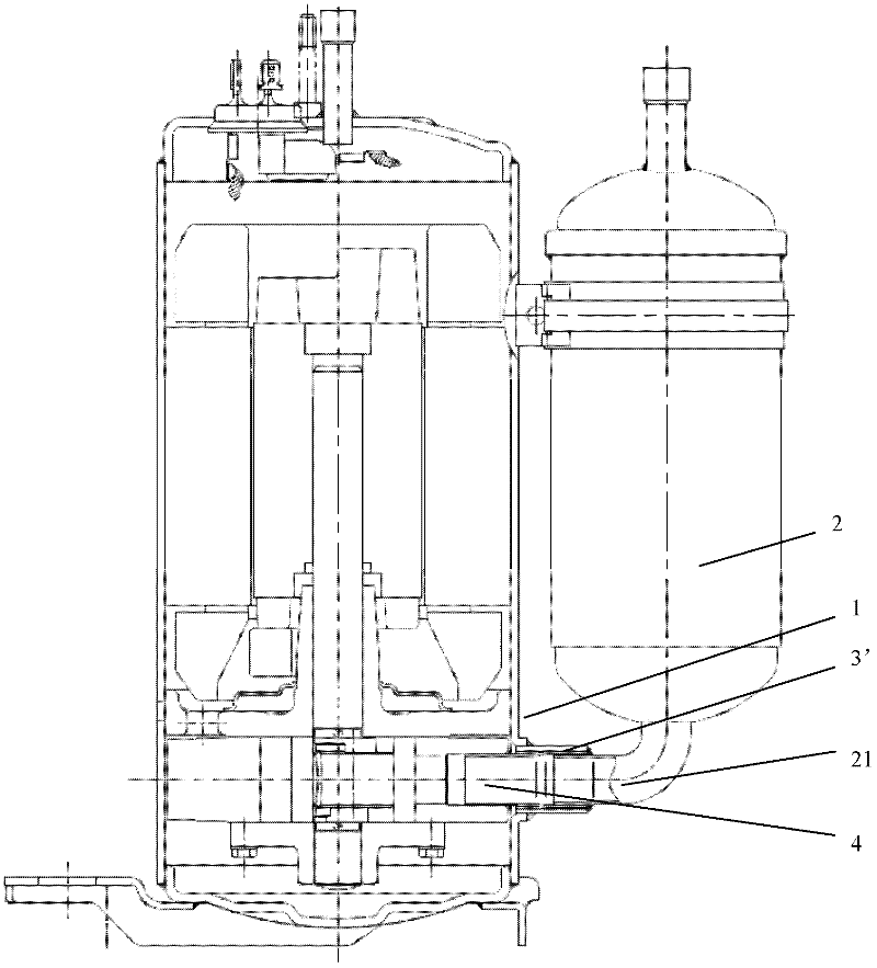
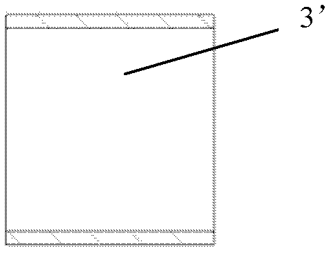
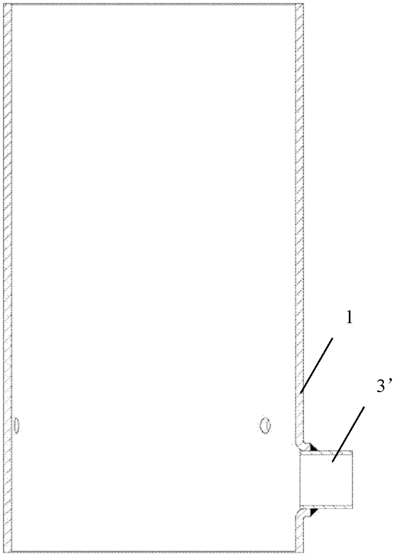
[0033] like Figure 7 As shown, the resistance welded pipe in this embodiment is an independent iron pipe A, the outer peripheral surface of one end is covered with a copper layer B to form a brazing position 32, and the other end exposes the iron base material to form an iron welding position 31. At the same time, the position of the iron welding position 31 is turned outward by about 40° to form a flange 33, which is matched with the shell 1 of the compressor. The shell 1 is a cylindrical structure, so the welded pipe should be welded with the cylindrical surface of the shell when the two are assembled. Therefore, preferably, the welded part of the shell 1 is formed by stamping such as Figure 4 As shown in the boss 11, the front section of the boss 11 is an inclined plane with the same valgus angle as...


PUM

PropertyMeasurementUnit
thicknessaaaaaaaaaa
melting pointaaaaaaaaaa

Abstract

The invention discloses a resistance welding tube and a manufacturing method and an application thereof. The resistance welding tube disclosed by the invention adopts an iron basis material and is provided with an iron welding position and a copper welding position, wherein the copper welding position is covered with a copper layer; and the iron basis material is exposed on the iron welding position. The manufacturing method provided by the invention is simple; a welding tube formed by compounding copper and iron is obtained, wherein the part for being used to be welded with the iron (such as a compressor shell) is an iron material; the iron materials can be welded by resistance welding; compared with the existing technology that the iron material and the copper material are welded by silver solder and flame welding, the welding cost and the welding difficulty are lowered, the welding mechanical strength of the manufacturing method is improved by above 30%, the pressure resistance strength is improved by above 20% and the welding airtight leakage rate is reduced by above 70%; and the part for being used to be welded with the copper (such as a compressor copper tube) is a copper material, and the copper materials can be still welded by flame welding.

Description

technical field [0001] The invention relates to a resistance welding pipe, its preparation method and application. Background technique [0002] In the existing welding methods, the welding of copper and copper generally uses copper solder as the welding material, and the welding is realized by flame heating; the welding of copper and iron generally uses silver solder to achieve welding through flame heating, or copper solder as the welding material , welding is achieved by flame heating or furnace; iron and iron are welded by resistance welding. [0003] However, in different technical fields, according to their special use requirements, the welding methods of their products will also have certain differences. Such as the existing air-conditioning compressor field, because its compressor is made up of compressor housing 1, motor, pump body and liquid accumulator 2, as figure 1 As shown, the compressor casing 1 and the accumulator 2 are connected by copper pipes. The way ...

Claims


Application Information

Patent Timeline
Patent Type & Authority Applications(China)
IPC IPC(8): B23K35/12B23P15/00
Inventor 陈金龙
Owner DONGGUAN JINRUI HARDWARE PROD
Why Eureka
Try Eureka