Bi-directional single fiber optical module and optical path detection method
An optical path detection and single-fiber bidirectional technology, which is applied in transmission monitoring/testing/fault measurement systems, electromagnetic wave transmission systems, electrical components, etc., can solve problems affecting business, reduce operating costs, shorten operation and maintenance, and alarm the effect of time
- Summary
- Abstract
- Description
- Claims
- Application Information
AI Technical Summary
Problems solved by technology
Method used
Image
Examples
Embodiment 1
[0061] In order to avoid the wavelength of the uplink and downlink services, the optical path detection is performed using light of a third wavelength different from the wavelength of the uplink and downlink services.
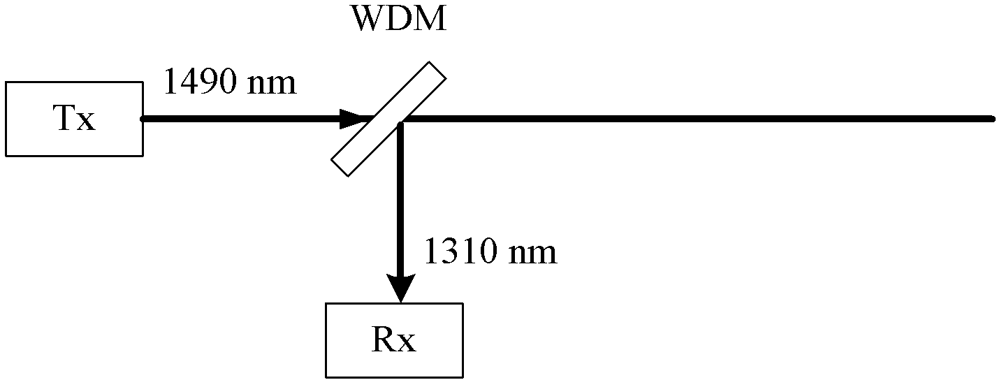
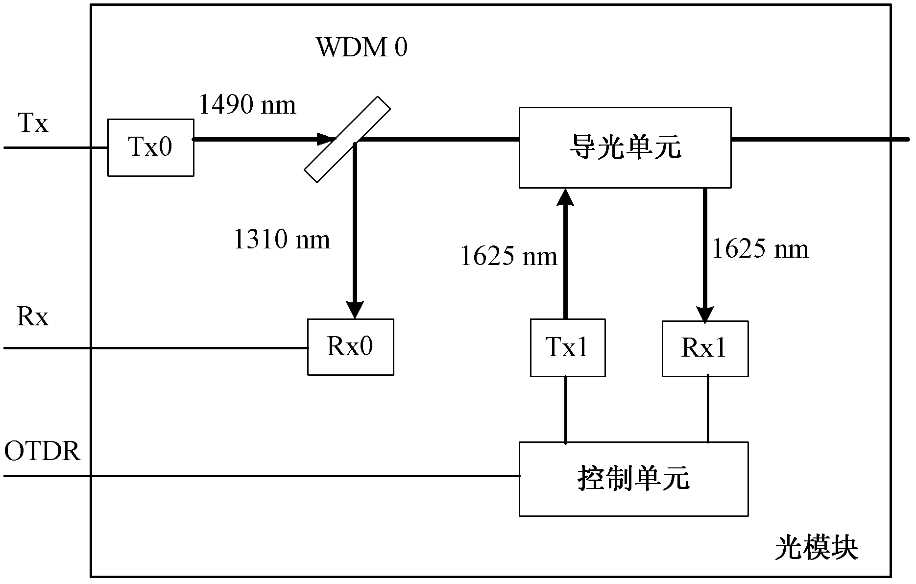
[0062] like image 3 As shown, the device is in the original BOSA (Bi-directional Optical Sub Assembly, single-fiber bidirectional optical module) composed of the first downlink optical transmitter Tx0, the first wavelength division multiplexing filter WDM0 and the first optical receiver Rx0 ) structure, a control unit, a light guide, a second downlink optical transmitter Tx1 of a third wavelength (such as 1625nm), a second wavelength division multiplexing filter WDM1 and a second optical receiver Rx1 are added. The WDM1 guides the light of the third wavelength, so that the service light does not enter the light guide. Through the newly added control unit, the optical path detection can be controlled and corresponding data processing can be performed. Wherein...
Embodiment 2
[0068] like Figure 4 As shown, on the basis of the structure of the above-mentioned first embodiment, the interrelationship of these devices is clarified.
[0069] The MAC chip of the OLT is connected to the optical module through four connecting lines, in which Tx0 Data and Tx0 Disable control the first downstream optical transmitter Tx0 through the first laser driver, while the connecting line Rx is locked through the LIA (Lock-In Amplifier) Amplifier) and TIA (Transimpedance Amplifier, Transimpedance Amplifier) to receive the data received by the first optical receiver Rx0, and the MAC chip of the OLT is connected to the control unit in the optical module through the OTDR connection line, which is used to start / stop the OTDR The control unit in the optical module is used to execute the command sent by the OLT MAC chip and perform data processing on the reflected light of the optical path detection light sent by the received Rx1 to obtain the OTDR data. Transfer it to ...
Embodiment 3
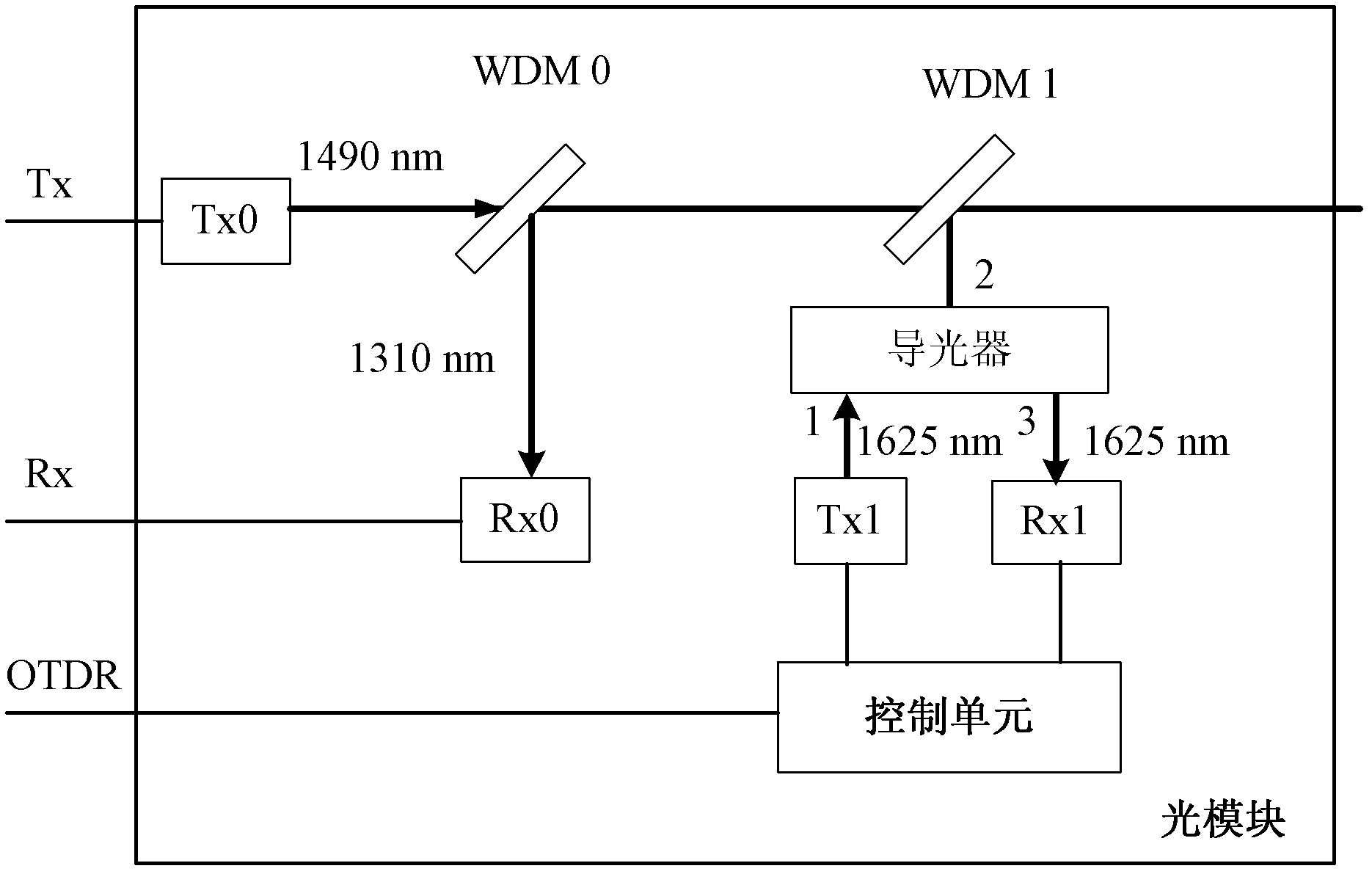
[0072] like Figure 5 As shown, in this embodiment, the device adds a control unit to the original BOSA structure composed of the first downlink optical transmitter Tx0, the first wavelength division multiplexing filter WDM0 and the first optical receiver Rx0 , a second wavelength division multiplexing filter WDM1, an optical splitter, a second downstream optical transmitter Tx1 for emitting optical path detection light of a third wavelength (eg, 1625 nm), and a second optical receiver Rx1.
[0073] The transmission process of its upstream and downstream business light is as follows: the first downstream optical transmitter Tx0 will send out a downlink business light with a wavelength of 1490nm for GPON or EPON, and a downlink business light with a wavelength of 1577nm for XG-PON or 10G-EPON. , through the first wavelength division multiplexing filter WDM0, the second wavelength division multiplexing filter WDM1 and the optical splitter to be guided to the optical fiber interf...
PUM
 Abstract
Description
Claims
Application Information
 - R&D
- Intellectual Property
- Life Sciences
- Materials
- Tech Scout
- Unparalleled Data Quality
- Higher Quality Content
- 60% Fewer Hallucinations
Browse by: Latest US Patents, China's latest patents, Technical Efficacy Thesaurus, Application Domain, Technology Topic, Popular Technical Reports.
© 2025 PatSnap. All rights reserved.Legal|Privacy policy|Modern Slavery Act Transparency Statement|Sitemap|About US| Contact US: help@patsnap.com


